P1639
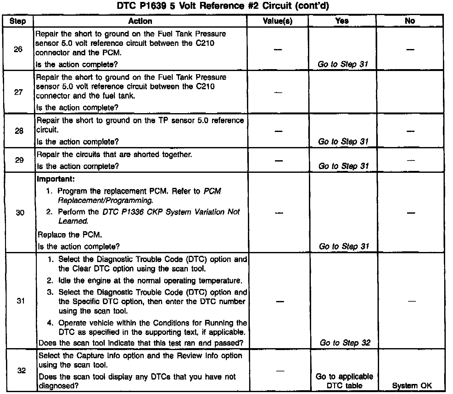
Diagnostic Chart:
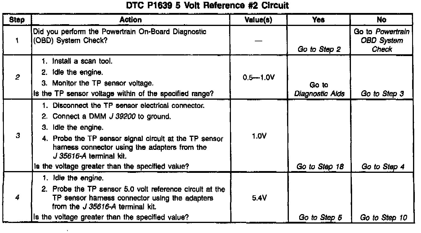
Diagnostic Chart:
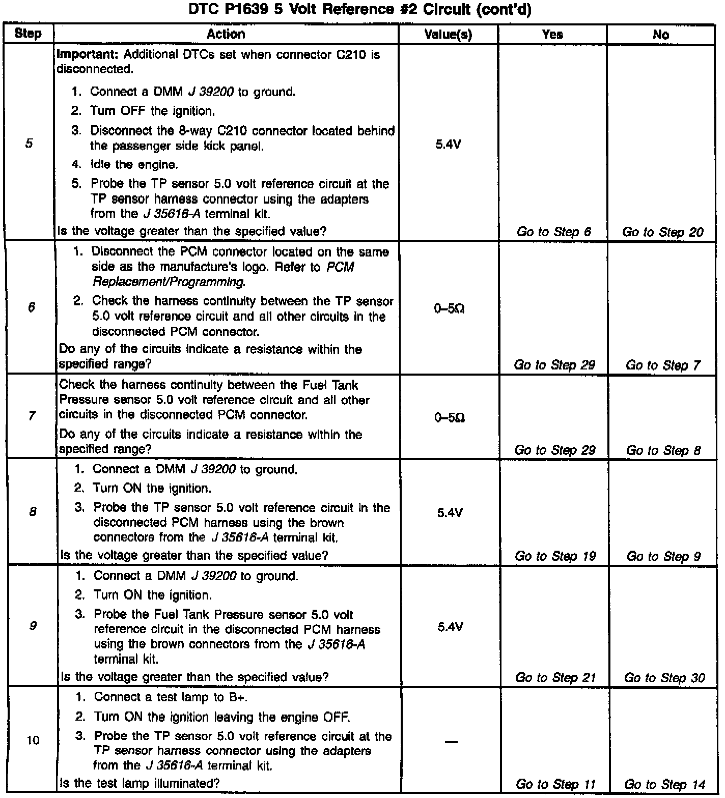
Diagnostic Chart:
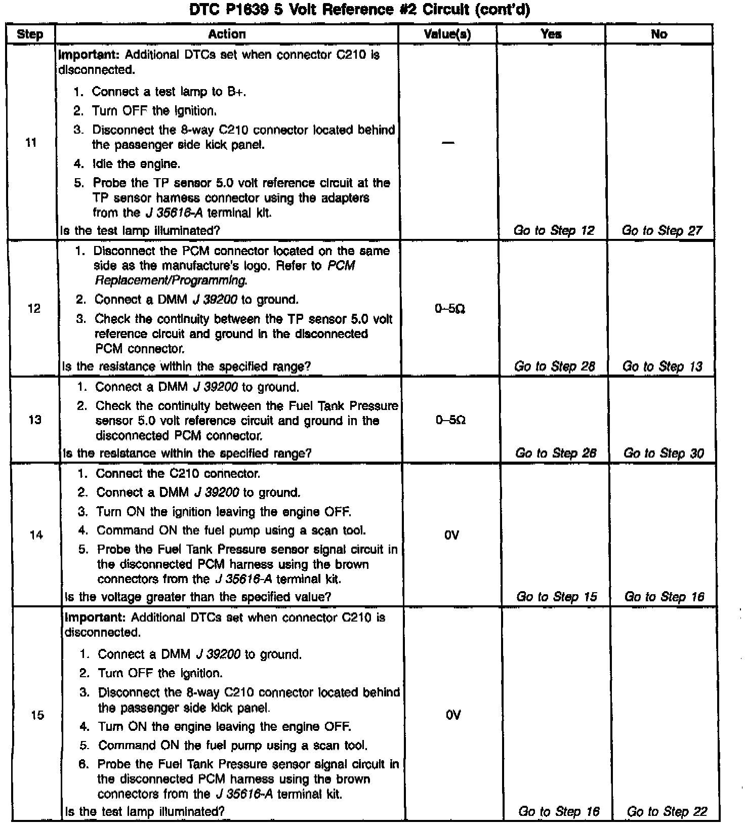
Diagnostic Chart:
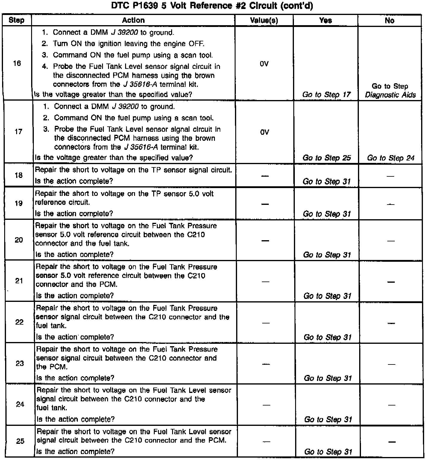
Diagnostic Chart:
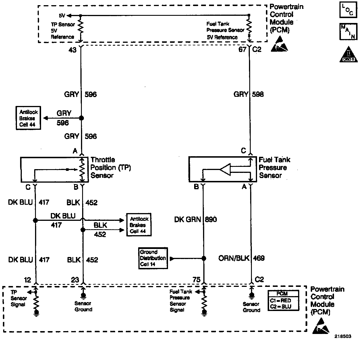
Wiring Diagram:
CIRCUIT DESCRIPTION
The PCM uses a common 5.0 Volt Reference circuit as a sensor feed to the Fuel Tank Pressure sensor, the Fuel Tank Level sensor and, the TP sensor.
The PCM monitors the voltage on the 5.0 Volt Reference circuit. This DTC sets if the voltage is out of range.
CONDITIONS FOR RUNNING THE DTC
The engine operating.
CONDITIONS FOR SETTING THE DTC
- The 5.0 volt reference circuit is out of range.
- The above condition is present for greater than 2 seconds.
ACTION TAKEN WHEN THE DTC SETS
- The PCM illuminates the Malfunction Indicator Lamp on the second consecutive drive trip that the diagnostic runs and fails.
- The PCM records the operating conditions at the time the diagnostic fails. The first time the diagnostic fails, the PCM stores this information in the Failure Records. If the diagnostic reports a failure on the second consecutive drive trip, the PCM records the operating conditions at the time of the failure. The PCM writes the conditions to the Freeze Frame and updates the Failure records.
CONDITIONS FOR CLEARING THE MIL/DTC
- The PCM turns the MIL OFF after three consecutive drive trips that the diagnostic runs and does not fail.
- A last test failed (current DTC) clears when the diagnostic runs and does not fail.
- A History DTC clears after forty consecutive warm-up cycles, if this or any other emission related diagnostic does not report any failures.
- The PCM battery voltage is interrupted.
- Use a scan tool in order to clear the MIL/DTC.
DIAGNOSTIC AIDS
A fuel level sensor (right tank) signal circuit that is shorted to B+ may set this DTC.
Using the Freeze Frame and/or Failure Records data may aid in locating an intermittent condition. If you cannot duplicate the DTC, the information included in the Freeze Frame and/or Failure Records data can help determine how many miles since the DTC set. The Fail Counter and Pass Counter can also help determine how many ignition cycles the diagnostic reported a pass and/or a fail. Operate vehicle within the same freeze frame conditions (RPM, load, vehicle speed, temperature etc.) that you observed. This will isolate when the DTC failed. For an intermittent condition, refer to Symptoms. Testing and Inspection
TEST DESCRIPTION
The numbers below refer to the step numbers on the Diagnostic Table.
2. This step verifies that the fault is present.
3. This step checks for the TP sensor signal circuit for being shorted to B+.
4. This step checks for the 5.0 volt reference circuit for being shorted to B+.
5. This step separates the circuit in order to determine if the short is forward or rearward of the connector.
6. This step checks for the TP sensor 5.0 volt reference circuit for being shorted to a circuit in the PCM harness.
7. This step checks for the Fuel Tank Pressure sensor 5.0 volt reference circuit for being shorted to a circuit in the PCM harness.
8. This step checks for a short to B+ on the TP sensor 5.0 volt reference circuit.
9. This step checks for a short to B+ on the Fuel Tank Pressure sensor 5.0 volt reference circuit.
10. This step checks the 5.0 volt circuit for a short to a ground.