Driver Information Center Switches Inoperative
- If instrument cluster diagnostic system check was performed, go to next step. If instrument cluster diagnostic system check was not performed, go to INSTRUMENT CLUSTER DIAGNOSTIC SYSTEM CHECK
under SELF-DIAGNOSTIC SYSTEM.
- Turn ignition off. Connect scan tool to Data Link Connector (DLC). See Figure
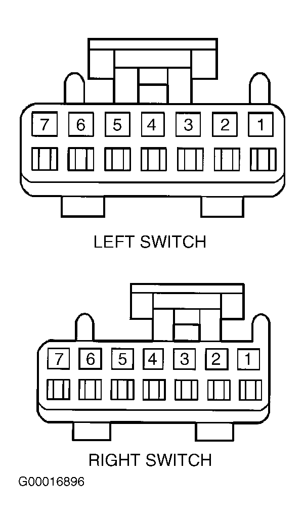
. Turn ignition on. Press and release each Driver Information Center (DIC) switch. See Figure
and Figure
. Using scan tool, select Instrument Panel Cluster (IPC) data list. Monitor DISPLAY MODE SWITCH, DISPLAY TRIP RESET SW, ENGLISH/METRIC SW, INFO RESET SWITCH, INFORMATION DOWN SWITCH, INFORMATION UP SWITCH, ON/OFF SWITCH and TRIP ODOMETER A/B SWITCH status. If status for each switch is ON when pressed and OFF when released, check for intermittent connections or faulty circuits. If status for each switch is not ON when pressed and not OFF when released, go to next step.
- If status for each switch is OFF when pressed, go to next step. If status for each switch is not OFF when pressed, go to step 5
.
- Monitor IGNITION 1 status on scan tool. If IGNITION 1 status is not ON, go to step 12
. If IGNITION 1 status is ON, go to step 14
.
- Turn parking lights on and cover ambient light sensor located on center of instrument panel defroster outlet. Monitor scan tool DIC switch status. Left DIC switch contains DSPL MODE, ENG/MET, TRIP RESET and TRIP A/B buttons. Right DIC switch contains ON/OFF, INFO RESET, INFO Down and INFO Up buttons. If scan tool does not indicate OFF status for all buttons contained in left or right DIC switch, go to next step. If scan tool indicates OFF status for all buttons contained in left or right DIC switch, go to step 11
.
- If scan tool always displays ON status for suspect switch, go to next step. If scan tool does not always display ON status for suspect switch, go to step 8
.
- Turn ignition off. Disconnect DIC switch connectors. See DRIVER INFORMATION CENTER SWITCHES
under REMOVAL & INSTALLATION. Turn ignition on. Monitor suspect DIC switch status on scan tool. If status is ON, go to step 9
. If status is not ON, go to step 13
.
- Turn ignition off. Disconnect DIC switch connectors. Connect a 3-amp fused jumper wire between suspect DIC switch terminal and ground. See DRIVER INFORMATION SWITCH CIRCUITS
table. Turn ignition on. Monitor suspect DIC switch status. If suspect DIC switch status is not ON, go to next step. If suspect DIC switch status is ON, go to step 13
.
- Check for short to ground in circuit for suspect switch. If circuit is okay, go to step 14
. If faulty circuit is found and repaired, go to step 17
.
- Check for open or high resistance in circuit for suspect switch. If circuit is okay, go to step 14
. If faulty circuit is found and repaired, go to step 17
.
- Check for open or high resistance in Black wire between suspect switch and ground. If circuit is okay, go to step 13
. If faulty circuit is found and repaired, go to step 17
.
- Check for open or short to voltage in Pink wire between IPC connector C2 terminal A3 and IGN 1 fuse (10-amp) located in rear fuse block. See Figure
. If circuit is okay, go to step 14
. If faulty circuit is found and repaired, go to step 17
.
- Check for poor connections at suspect DIC switch connector. If connections are okay, go to step 15
. If faulty connections are found and repaired, go to step 17
.
- Check for poor connections at IPC connector. If connections are okay, go to step 16
. If faulty connections are found and repaired, go to step 17
.
- Replace suspect DIC switch. See DRIVER INFORMATION CENTER SWITCHES
under REMOVAL & INSTALLATION. After repairs, go to step 17
.
- Replace IPC. See INSTRUMENT PANEL CLUSTER
under REMOVAL & INSTALLATION. After repairs, go to next step.
- After repairs, recheck operation of DIC switches. If switches operate properly, repair is complete. If switches do not operate properly, go to step 2
.
DRIVER INFORMATION SWITCH CIRCUITS
| Switch Identification |
DIC Terminal No. |
IPC Connector C2 Terminal |
Wire Color |
| Left Switch |
| DSPL MODE |
4 |
A2 |
Pink |
| ENG/MET |
2 |
A3 |
Light Blue |
| TRIP RESET |
6 |
A4 |
Light Green |
| TRIP A/B |
5 |
A5 |
Dark Blue |
| Ground For Left Switch |
1 |
N/A |
Black |
| Right Switch |
| INFO Up Arrow |
1 |
A9 |
Orange |
| INFO Down Arrow |
2 |
A8 |
Pink/White |
| INFO RESET |
3 |
A7 |
Orange |
| ON/OFF |
5 |
A6 |
Dark Green/White |
| Ground For Right Switch |
6 |
N/A |
Black |
 Courtesy of GENERAL MOTORS CORP.