Pinpoint Test U: The PRNDL Indicator is Never/Always On (If Equipped)
Instrumentation, Message Center and Warning Chimes
Pinpoint Test U: The PRNDL Indicator is Never/Always On (If Equipped)
Refer to Wiring Diagram Set 60, Instrument Cluster for schematic and connector information Electrical Diagrams.
NOTE: The PRNDL is only available on column shift vehicles.
Normal Operation
The Instrument Cluster (IC) receives the transmission range status from the Transmission Control Module (TCM) over the High Speed Controller Area Network (HS-CAN) communication bus. Column shift vehicles use a park detect switch (part of the brake shift interlock) to signal the IC (Instrument Cluster) that the shift lever is fully seated in the park position. The IC (Instrument Cluster) compares the park detect switch input with the transmission range status sent from the TCM (Transmission Control Module). The IC (Instrument Cluster) provides a reference voltage to the brake shift interlock on the brake shift interlock input circuit. When the gearshift is in PARK (P), the brake shift indicator routes the reference voltage to ground, pulling the circuit low to the IC (Instrument Cluster). When the gearshift is moved out of PARK (P), the brake shift interlock opens the ground sending the reference voltage high. If the PRNDL information is missing from the TCM (Transmission Control Module), the IC (Instrument Cluster) sets DTC U0101 or if the IC (Instrument Cluster) sees a signal from the park detect switch indicating the shifter is in PARK (P) with a conflicting PRNDL input, the IC (Instrument Cluster) defaults the PRNDL display to blank (no PRNDL display).
NOTE: If DTC U0101 is set, other symptoms may include the Overdrive (O/D) off indicator or the powertrain malfunction (wrench) message center indicator ON.
- DTC C1945 (Park Switch Indicates Park with Vehicle Moving)- a continuous memory DTC that sets if the IC (Instrument Cluster) detects a short to ground on the park detect switch input circuit, pulling the circuit low with a Vehicle Speed Sensor (VSS) input over 16 km/h (10 mph), indicating that the vehicle is in motion.
This pinpoint test is intended to diagnose the following:
- Wiring, terminals or connectors
- Brake shift interlock
- IC (Instrument Cluster)
PINPOINT TEST U : THE PRNDL INDICATOR IS NEVER/ALWAYS ON (IF EQUIPPED)
NOTICE: Use the correct probe adapter(s) when making measurements. Failure to use the correct probe adapter(s) may damage the connector.
U1 CHECK THE PRNDL DISPLAY PARK OPERATION
- Ignition ON.
- Shift the selector lever through the different gear positions while observing the PRNDL display.
- Place the selector lever in the PARK (P) position.
- Ignition OFF.
- Observe the PRNDL display immediately after turning the key off.
Does the PRNDL display the different ranges according to the selector lever position then display P for approximately 5 seconds when the key is turned off?
Yes
The system is functioning correctly at this time.
No
GO to U2.
U2 RETRIEVE AND RECORD THE IC (Instrument Cluster) DTCs FROM THE SELF-TEST
- Check for recorded IC (Instrument Cluster) DTCs from the self-test.
Are any DTCs recorded?
Yes
For all DTCs, REPEAT the self-test. CLEAR the DTCs. DRIVE the vehicle above 16 km/h (10 mph) for more than 5 seconds.
For DTC C1945, GO to U6.
For DTC U0101, GO to Pinpoint Test AU. Pinpoint Test AU: DTC U0101
For all other DTCs, REFER to DTC Charts. Instrumentation, Message Center and Warning Chimes
No
GO to U3.
U3 RETRIEVE AND RECORD THE DTCs FROM THE PCM KOEO (Key ON Engine OFF) SELF-TEST
- Check for recorded PCM DTCs from the Key ON Engine OFF (KOEO) self-test.
Are any PCM DTCs recorded?
Yes
REFER to Computers and Control Systems Information.
No
GO to U4.
U4 RETRIEVE AND RECORD THE DTCs FROM THE TCM (Transmission Control Module) SELF-TEST
- Check for recorded TCM (Transmission Control Module) DTCs from the self-test.
Are any TCM (Transmission Control Module) DTCs recorded?
Yes
REFER to Automatic Transmission/Transaxle &/or Transmission Control Systems.
No
GO to U5.
U5 CARRY OUT THE IC (Instrument Cluster) DEALER TEST MODE
- Ignition ON.
- Verify that the transmission selector lever is fully seated in the PARK (P) position.
- Enter the IC (Instrument Cluster) dealer test mode. Scroll through the displays until PRKDETSW is displayed and note the park detect switch status.
Does the self-test indicate G?
Yes
GO to U8.
No
GO to U6.
U6 CHECK THE BRAKE SHIFT INTERLOCK OPERATION
- Ignition OFF.
- Disconnect: Brake Shift Interlock C2008.
- Clear the DTCs. DRIVE the vehicle above 16 km/h (10 mph) for more than 5 seconds. Retrieve the IC (Instrument Cluster) continuous memory DTCs.
Is DTC C1945 still present?
Yes
GO to U7.
No
INSTALL a new brake shift interlock. TEST the system for normal operation.
U7 CHECK THE BRAKE SHIFT INTERLOCK INPUT CIRCUIT FOR AN OPEN OR SHORT TO GROUND
- Ignition OFF.
- Disconnect: IC (Instrument Cluster) C220.
- Disconnect: Brake Shift Interlock C2008.
- Measure the resistance between the IC (Instrument Cluster) C220-26, circuit CET53 (BU/OG), harness side and the brake shift interlock C2008-2, circuit CET53 (BU/OG), harness side; and between the IC (Instrument Cluster) C220-26, circuit CET53 (BU/OG), harness side and ground.
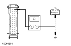
Is the resistance less than 5 ohms between the IC (Instrument Cluster) and the brake shift interlock, and greater than 10,000 ohms between the IC (Instrument Cluster) and ground?
Yes
GO to U8.
No
REPAIR circuit CET53 (BU/OG) in question. REPEAT the self-test. CLEAR the DTCs.
U8 CHECK FOR CORRECT IC (Instrument Cluster) OPERATION
- Disconnect all the IC (Instrument Cluster) connectors.
- Check for:
- corrosion
- damaged pins
- pushed-out pins
- Connect all the IC (Instrument Cluster) connectors and make sure they seat correctly.
- Operate the system and verify the concern is still present.
Is the concern still present?
Yes
INSTALL a new IC (Instrument Cluster). REFER to Instrument Cluster (IC) . TEST the system for normal operation.
No
The system is operating correctly at this time. The concern may have been caused by a loose or corroded connector.