Installation
3UR-FE ENGINE MECHANICAL: CAMSHAFT: INSTALLATION
1. INSTALL CAMSHAFT BEARING CAP RH
(a) Apply a light coat of engine oil to the camshaft journals, camshaft housings and bearing caps.
(b) Install the No. 1 and No. 2 camshafts to the camshaft housing.
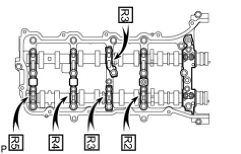
(c) Confirm the marks and numbers on the camshaft bearing caps and place them in their proper positions and directions.
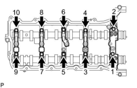
(d) Temporarily install the 10 bolts in the order shown in the illustration.
2. INSTALL CAMSHAFT HOUSING SUB-ASSEMBLY RH
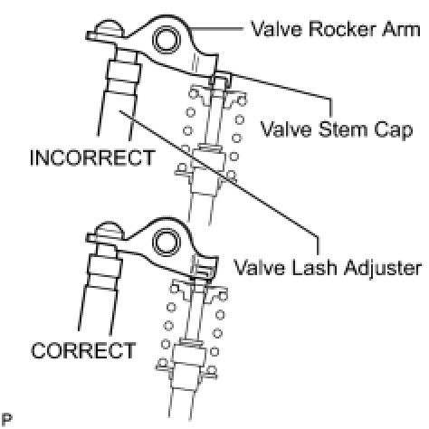
(a) Make sure that the valve rocker arms are installed as shown in the illustration.
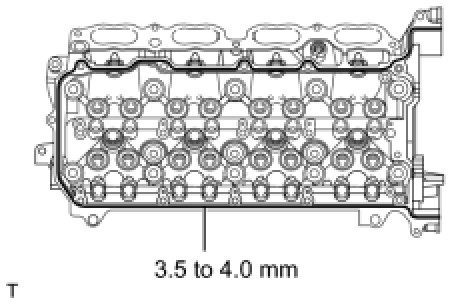
(b) Apply seal packing in a continuous line as shown in the illustration.
Seal packing:
Toyota Genuine Seal Packing Black, Three Bond 1207B or equivalent
Standard seal diameter:
3.5 to 4.0 mm (0.138 to 0.157 in.)
NOTICE:
- Remove any oil from the contact surface.
- Install the camshaft housing within 3 minutes and tighten the bolts within 15 minutes after applying seal packing.
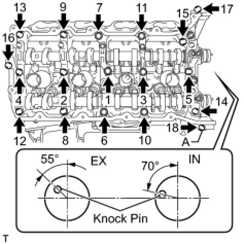
(c) Install the camshaft housing, and install the 18 bolts in the order shown in the illustration.
for bolt A - Torque: 10 Nm (102 kgf-cm, 7 ft-lbf)
except bolt A - Torque: 30 Nm (306 kgf-cm, 22 ft-lbf)
NOTICE:
- Do not start the engine for at least 2 hours after the installation.
- Make sure that the knock pin of the camshaft is positioned as shown in the illustration before installing the camshaft housing.
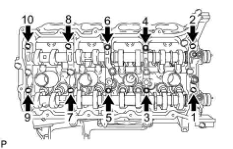
(d) Tighten the 10 bolts in the order shown in the illustration.
Torque: 16 Nm (163 kgf-cm, 12 ft-lbf)
NOTICE:
Thoroughly wipe clean any seal packing.
3. INSTALL CAMSHAFT BEARING CAP LH
(a) Apply a light coat of engine oil to the camshaft journals, camshaft housings and bearing caps.
(b) Install the No. 3 and No. 4 camshafts to the camshaft housing.
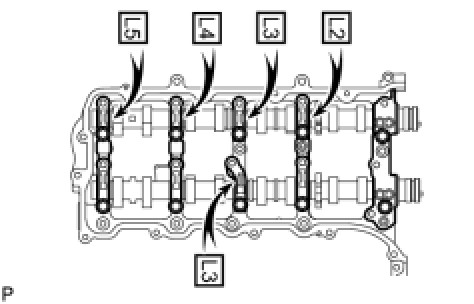
(c) Confirm the marks and numbers on the camshaft bearing caps and place them in their proper positions and directions.
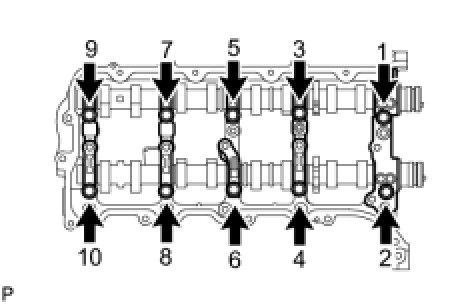
(d) Temporarily install the 10 bolts in the order shown in the illustration.
4. INSTALL CAMSHAFT HOUSING SUB-ASSEMBLY LH
(a) Make sure that the valve rocker arms are installed as shown in the illustration.
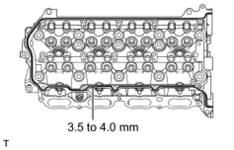
(b) Apply seal packing in a continuous line as shown in the illustration.
Seal packing:
Toyota Genuine Seal Packing Black, Three Bond 1207B or equivalent
Standard seal diameter:
3.5 to 4.0 mm (0.138 to 0.157 in.)
NOTICE:
- Remove any oil from the contact surface.
- Install the camshaft housing within 3 minutes and tighten the bolts within 15 minutes after applying seal packing.
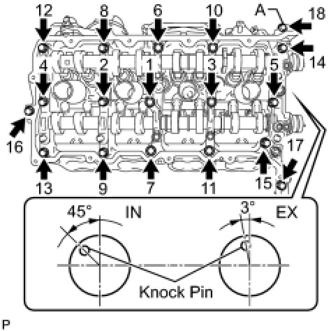
(c) Install the camshaft housing, and install the 18 bolts in the order shown in the illustration.
for bolt A - Torque: 10 Nm (102 kgf-cm, 7 ft-lbf)
except bolt A - Torque: 30 Nm (306 kgf-cm, 22 ft-lbf)
NOTICE:
- Do not start the engine for at least 2 hours after the installation.
- Make sure that the knock pin of the camshaft is positioned as shown in the illustration before installing the camshaft housing.
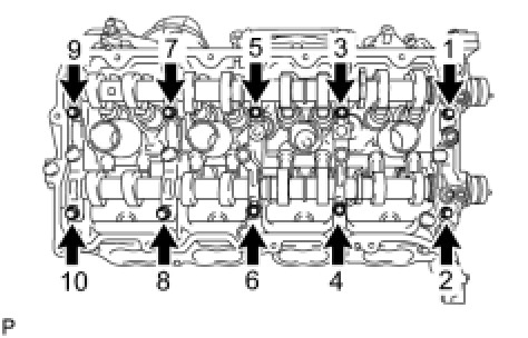
(d) Tighten the 10 bolts in the order shown in the illustration.
Torque: 16 Nm (163 kgf-cm, 12 ft-lbf)
NOTICE:
Thoroughly wipe clean any seal packing.
5. INSTALL CRANKSHAFT TIMING GEAR KEY [1][2]Reassembly
6. SET NO. 1 CYLINDER TO TDC/COMPRESSION [1][2]Reassembly
7. INSTALL NO. 2 CHAIN TENSIONER ASSEMBLY [1][2]Reassembly
8. INSTALL NO. 1 CHAIN SUB-ASSEMBLY RH [1][2]Reassembly
9. INSTALL NO. 1 CHAIN VIBRATION DAMPER RH [1][2]Reassembly
10. INSTALL NO. 1 CHAIN TENSIONER SLIPPER RH [1][2]Reassembly
11. INSTALL NO. 1 CHAIN TENSIONER ASSEMBLY RH [1][2]Reassembly
12. INSTALL NO. 3 CHAIN TENSIONER ASSEMBLY [1][2]Reassembly
13. INSTALL NO. 1 CHAIN SUB-ASSEMBLY LH [1][2]Reassembly
14. INSTALL NO. 1 CHAIN TENSIONER SLIPPER LH [1][2]Reassembly
15. INSTALL NO. 1 CHAIN TENSIONER ASSEMBLY LH [1][2]Reassembly
16. INSTALL NO. 1 CHAIN VIBRATION DAMPER LH [1][2]Reassembly
17. TIGHTEN CAMSHAFT TIMING GEAR [1][2]Reassembly
18. CHECK NO. 1 CYLINDER TO TDC/COMPRESSION [1][2]Reassembly
19. INSTALL WATER INLET PIPE [1][2]Installation
20. INSTALL TIMING CHAIN COVER SUB-ASSEMBLY [1][2]Installation
21. INSTALL SPARK PLUG TUBE GASKET [1][2]Reassembly
22. INSTALL CYLINDER HEAD COVER SUB-ASSEMBLY LH [1][2]Installation
23. INSTALL CYLINDER HEAD COVER SUB-ASSEMBLY RH [1][2]Installation
24. INSTALL IGNITION COIL ASSEMBLY [1][2]Installation
25. INSTALL CRANKSHAFT TIMING GEAR KEY [1][2]Reassembly
26. CONNECT WIRE HARNESS CLAMP BRACKET [1][2]Installation
27. INSTALL CRANKSHAFT PULLEY [1][2]Installation
28. INSTALL NO. 1 IDLER PULLEY SUB-ASSEMBLY [1][2]Installation
29. INSTALL WATER PUMP PULLEY [1][2]Installation
30. INSTALL WATER INLET HOUSING [1][2]Installation
31. INSTALL AIR PIPE SUB-ASSEMBLY [1][2]Installation
32. INSTALL NO. 1 ENGINE COVER Installation
33. INSTALL NO. 2 ENGINE COVER Installation
34. INSTALL FRONT WATER BY-PASS JOINT [1][2]Installation
35. INSTALL WATER BY-PASS PIPE SUB-ASSEMBLY [1][2]Installation
36. INSTALL NO. 1 WATER BY-PASS HOSE [1][2]Installation
37. INSTALL GENERATOR ASSEMBLY Installation
38. CONNECT OIL COOLER PIPE ASSEMBLY Installation
39. INSTALL ENGINE OIL LEVEL DIPSTICK GUIDE Installation
40. CONNECT VANE PUMP ASSEMBLY [1][2]Installation
41. INSTALL INTAKE MANIFOLD Installation
42. INSTALL OIL FILTER BRACKET (w/o Oil Cooler) [1][2]Installation
43. INSTALL OIL FILTER BRACKET (w/ Oil Cooler) Installation
44. INSTALL NO. 1 OIL COOLER BRACKET (w/ Oil Cooler) Installation
45. INSTALL NO. 2 WATER BY-PASS PIPE SUB-ASSEMBLY (w/ Oil Cooler) [1][2]Installation
46. INSTALL OIL PRESSURE SENDER GAUGE ASSEMBLY Installation
47. INSTALL OIL FILTER ELEMENT Replacement
48. CONNECT NO. 2 FUEL TUBE SUB-ASSEMBLY [1][2]Installation
49. CONNECT COOLER COMPRESSOR ASSEMBLY [1][2]Installation
50. CONNECT NO. 2 WATER BY-PASS PIPE [1][2]Installation
51. CONNECT AIR PUMP HOSE AND WIRE HARNESS [1][2]Installation
52. CONNECT ENGINE WIRE [1][2]Installation
53. INSTALL RADIATOR ASSEMBLY [1][2]Installation
54. INSTALL FAN SHROUD Installation
55. INSTALL NO. 2 RADIATOR HOSE
56. INSTALL NO. 1 RADIATOR HOSE
57. INSTALL AIR CLEANER ASSEMBLY Installation
58. INSTALL AIR CLEANER HOSE ASSEMBLY Installation
59. INSTALL COWL TOP VENTILATOR LOUVER SUB-ASSEMBLY Installation
60. INSTALL HOOD TO COWL TOP SEAL Installation
61. INSTALL FRONT FENDER MAIN SEAL LH Installation
62. INSTALL FRONT FENDER MAIN SEAL RH Installation
63. INSTALL FRONT WIPER ARM LH Installation
64. INSTALL FRONT WIPER ARM RH Installation
65. INSTALL RADIATOR SIDE DEFLECTOR RH (w/o Air Cooled Transmission Oil Cooler) Installation
66. INSTALL RADIATOR SIDE DEFLECTOR LH Installation
67. INSTALL RADIATOR GRILLE Installation
68. ADD ENGINE OIL Replacement
69. ADD ENGINE COOLANT Service and Repair
70. CONNECT CABLE TO NEGATIVE BATTERY TERMINAL
NOTICE:
When disconnecting the cable, some systems need to be initialized after the cable is reconnected Repair Instruction - Initialization.
71. INSPECT FOR OIL LEAK Replacement
72. INSPECT FOR COOLANT LEAK Testing and Inspection
73. INSPECT ENGINE OIL LEVEL Testing and Inspection
74. INSPECT IGNITION TIMING Engine
75. INSPECT ENGINE IDLE SPEED Engine
76. INSTALL FRONT FENDER APRON SEAL FRONT RH Installation
77. INSTALL FRONT FENDER APRON SEAL FRONT LH Installation
78. INSTALL NO. 2 ENGINE UNDER COVER Installation
79. INSTALL NO. 1 ENGINE UNDER COVER SUB-ASSEMBLY Installation
80. INSTALL FRONT FENDER SPLASH SHIELD SUB-ASSEMBLY LH Installation
81. INSTALL FRONT FENDER SPLASH SHIELD SUB-ASSEMBLY RH Installation
82. INSTALL V-BANK COVER SUB-ASSEMBLY Installation
83. INSTALL UPPER RADIATOR SUPPORT SEAL Installation
84. INSTALL ENGINE ROOM SIDE COVER LH Installation
85. INSTALL ENGINE ROOM SIDE COVER RH Removal