Pinpoint Test AT: DTCs B1045, B1047, B1048, B1049, B104B, B104C, B104D, B1052, B1053, B1054, B1055, B1057, B1058, B1059 and B10
Air Bag and Safety Belt Pretensioner Supplemental Restraint System (SRS)
Pinpoint Tests
Pinpoint Test AT: DTCs B1045, B1047, B1048, B1049, B104B, B104C, B104D, B1052, B1053, B1054, B1055, B1057, B1058, B1059 and B10AC
Refer to Wiring Diagram Set 46, Supplemental Restraint System for schematic and connector information. Diagrams By Number
Normal Operation
The Restraints Control Module (RCM) monitors all the Supplemental Restraint System (SRS) components for a cross link between the circuits of another SRS component. If the RCM detects a short between the circuits of the SRS components, it will store DTC B2792 in memory and send a message to the Instrument Cluster (IC) module to illuminate the air bag warning indicator.
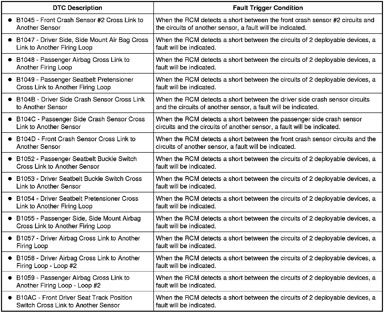
This pinpoint test is intended to diagnose the following:
- Wiring, terminals or connectors
- RCM
PINPOINT TEST AT: DTCs - B1045, B1047, B1048, B1049, B104B, B104C, B104D, B1052, B1053, B1054, B1055, B1057, B1058, B1059 AND B10AC
WARNING: Never probe the electrical connectors on air bag, Safety Canopy(R) or side air curtain modules. Failure to follow this instruction may result in the accidental deployment of these modules, which increases the risk of serious personal injury or death.
WARNING: Never disassemble or tamper with safety belt buckle/retractor pretensioners or adaptive load limiting retractors or probe the electrical connectors. Failure to follow this instruction may result in the accidental deployment of the safety belt pretensioners or adaptive load limiting retractors which increases the risk of serious personal injury or death.
WARNING: Always tighten the fasteners of the restraints control module (RCM) and impact sensor (if equipped) to the specified torque. Failure to do so may result in incorrect restraint system operation, which increases the risk of personal injury or death in a crash.
NOTICE: Use the correct probe adapter(s) when making measurements. Failure to use the correct probe adapter(s) may damage the connector.
NOTE: Most faults are due to connector and/or wiring concerns. Carry out a thorough inspection and verification before proceeding with the pinpoint test. Inspection and Verification
NOTE: SRS components should only be disconnected or reconnected when instructed to do so within a pinpoint test step. Failure to follow this instruction may result in incorrect diagnosis of the SRS.
NOTE: Always make sure the correct SRS component is being installed. Parts released for other vehicles may not be compatible even if they appear physically similar. Check the part number listed in the Ford Catalog Advantage(TM) or equivalent to make sure the correct component is being installed. If an incorrect SRS component is installed, DTCs may set.
NOTE: The SRS must be fully operational and free of faults before releasing the vehicle to the customer.
-------------------------------------------------
AT1 RETRIEVE RCM DTCs
NOTE: All RCM diagnosis will be carried out using Continuous Memory Diagnostic Trouble Codes (CMDTCs) and status information. Refer to DTC Fault Reporting and Status Information. DTC Fault Reporting and Status Information
- Ignition ON.
- Enter the following diagnostic mode on the scan tool: Self Test - RCM.
- Select the DTC and view DTC Status information.
- Does the status information for any pair of cross link DTCs indicate a fault was present at the time of request?
Yes
This fault cannot be cleared until it is corrected and the DTC is no longer retrieved during the self-test. GO to AT2.
No
This is an intermittent fault. The DTC Status information indicates the fault was not present at time of request. GO to AT4.
-------------------------------------------------
AT2 CHECK THE DEPLOYABLE CIRCUITS FOR A CROSS LINK FAULT
- Ignition OFF.
- Depower the SRS. Refer to Supplemental Restraint System (SRS) Depowering and Repowering Supplemental Restraint System (SRS) Depowering and Repowering.
- Disconnect: RCM C310A and C310B.
- Disconnect ALL of the affected deployable devices.
- Using the following chart, measure the resistance between the circuits of the affected deployable devices.
Deployable Devices
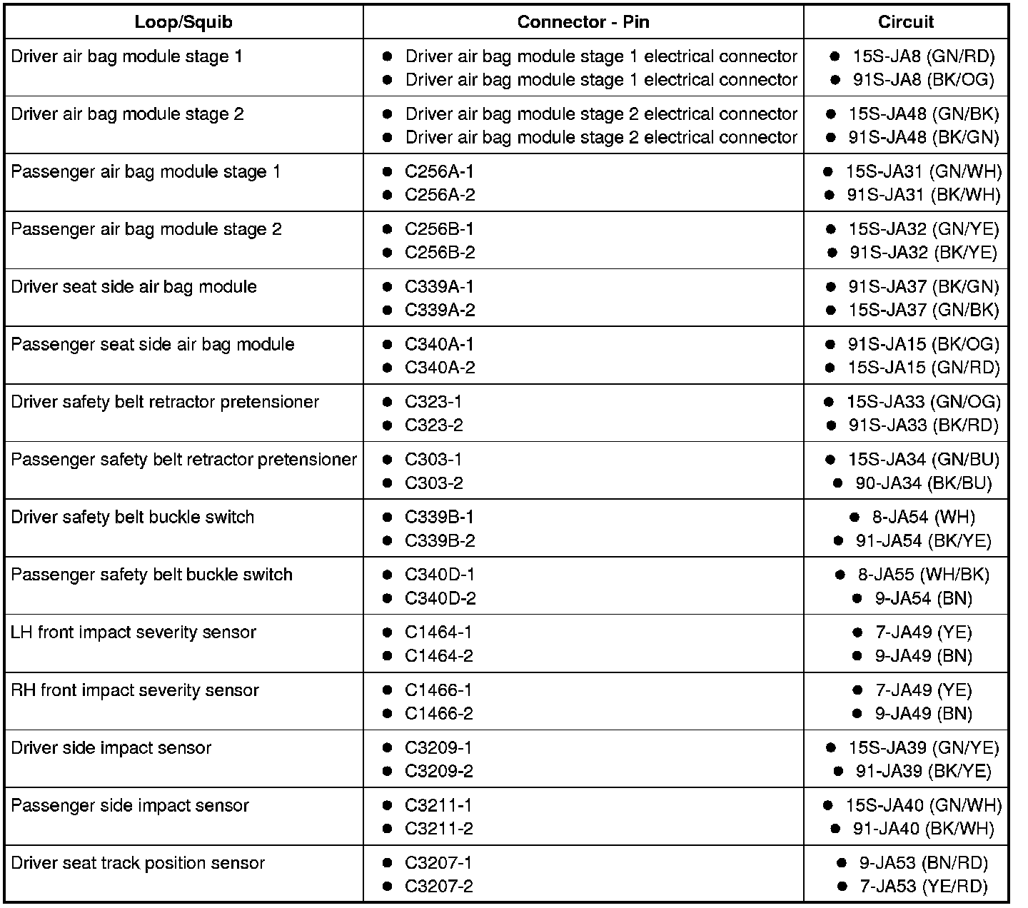
- Are the resistances greater than 10,000 ohms between the affected circuits?
Yes
GO to AT3.
No
REPAIR the affected circuits.
Refer to Wiring Diagram Set 46, Supplemental Restraint System for schematic and connector information. Diagrams By Number
GO to AT5.
-------------------------------------------------
AT3 CONFIRM THE RCM FAULT
NOTE: Make sure all restraint system components and the RCM electrical connectors are connected before carrying out the self-test. If not, DTCs will be recorded.
- Ignition OFF.
- Depower the SRS. Refer to Supplemental Restraint System (SRS) Depowering and Repowering Supplemental Restraint System (SRS) Depowering and Repowering.
- Prior to reconnecting any previously disconnected SRS component:
- inspect connector(s) (including any in-line connectors) for pushed-out, loose or spread terminals and loose or frayed wire connections at terminals.
- inspect wire harness for any damage, pinched, cut or pierced wires.
- inspect RCM C310A and C310B Connector Position Assurance (CPA) lever/lock for correct operation. Refer to Restraints Control Module (RCM) Service and Repair.
- repair any concerns found.
Refer to Wiring Diagram Set 5, Connector Repair Procedures for schematic and connector information. Diagrams By Number
- Connect: RCM C310A and C310B.
- Connect: All Previously Disconnected SRS Components.
- Repower the SRS. Do not prove out the SRS at this time. Refer to Supplemental Restraint System (SRS) Depowering and Repowering Supplemental Restraint System (SRS) Depowering and Repowering.
- Ignition ON.
- Enter the following diagnostic mode on the scan tool: Self Test - RCM.
- Select the DTC and view DTC Status information.
- Does the status information for any pair of cross link DTCs indicate a fault was present at the time of request?
Yes
INSTALL a new RCM. REFER to Restraints Control Module (RCM) Service and Repair. GO to AT5.
No
In the process of diagnosing the fault, the fault condition has become intermittent. Do not install any new SRS components at this time. SRS components should only be installed when directed to do so in the pinpoint test. GO to AT4.
-------------------------------------------------
AT4 CHECK FOR AN INTERMITTENT FAULT
- Ignition OFF.
- Depower the SRS. Refer to Supplemental Restraint System (SRS) Depowering and Repowering Supplemental Restraint System (SRS) Depowering and Repowering.
- If a cross link fault for driver air bag stage 1 or 2 is present, remove the driver air bag module. Refer to Driver Air Bag Module Driver Air Bag Module.
- If a cross link fault for passenger air bag module stage 1 or 2 is present, remove passenger air bag module and disconnect C256A and C256B. Refer to Passenger Air Bag Module Passenger Air Bag Module.
- If a cross link fault for driver side air bag is present, disconnect the driver seat bulkhead connector.
- If a cross link fault for passenger seat side air bag is present, disconnect the passenger seat bulkhead connector.
- If a cross link fault for driver safety belt retractor pretensioner is present continuous, remove and disconnect the driver safety belt retractor pretensioner C323. Refer to Safety Belt System Service and Repair.
- If a cross link fault for passenger safety belt retractor pretensioner is present continuous, remove and disconnect the passenger safety belt retractor pretensioner C303. Refer to Safety Belt System Service and Repair.
- Repower the SRS. Do not prove out the SRS at this time. Refer to Supplemental Restraint System (SRS) Depowering and Repowering Supplemental Restraint System (SRS) Depowering and Repowering.
- Ignition ON.
- Enter the following diagnostic mode on the scan tool: Self Test - RCM.
- Select the DTC and view DTC Status information.
- Does the status information for any pair of cross link DTCs indicate a fault was present at the time of request?
Yes
The fault condition is now present. Do not clear any DTCs until all DTC concerns have been resolved. GO to AT2.
No
The fault is not present and cannot be recreated at this time. Do not install any new SRS components at this time. SRS components should only be installed when directed to do so in the pinpoint test. GO to AT5.
-------------------------------------------------
AT5 CHECK FOR ADDITIONAL SRS DTCs
- Ignition OFF.
- WARNING: Turn the ignition OFF and wait one minute to deplete the backup power supply. Failure to follow this instruction may result in serious personal injury or death in the event of an accidental deployment.
- Reconnect all SRS components (if previously disconnected).
- If previously directed to depower the SRS, repower the SRS. Do not prove out the SRS at this time. Refer to Supplemental Restraint System (SRS) Depowering and Repowering Supplemental Restraint System (SRS) Depowering and Repowering.
- Ignition ON.
- Enter the following diagnostic mode on the scan tool: Self Test - Restraints.
- NOTE: When selecting Restraints from the Self Test menu, DTCs will be retrieved from the RCM and OCSM.
- Does the status information for any RCM DTC indicate a fault is present and/or are any OCSM on-demand DTCs retrieved?
Yes
Do not clear any DTCs until all DTC concerns have been resolved. GO to the DTC Charts for pinpoint test direction. Diagnostic Trouble Code Tests and Associated Procedures
No
CLEAR all RCM and OCSM CMDTCs. PROVE OUT the SRS. Repair is complete. RETURN the vehicle to the customer.
-------------------------------------------------