Pinpoint Test L: The ABS Warning Indicator Is Always On
Instrumentation and Warning Chimes
Pinpoint Tests
Pinpoint Test L: The ABS Warning Indicator Is Always On
Refer to wiring Diagram Set 60, Instrument Cluster for schematic and connector information. Diagrams By Number
Normal Operation
The Instrument Cluster (IC) receives the ABS status from the ABS module through hardwired circuitry. When an ABS concern is present, the ABS module sends the IC a command to illuminate the ABS warning indicator. If the IC detects a fault condition in the ABS, the IC turns on the ABS warning indicator.
- DTC C1221 (ABS Warning Lamp Output Circuit Short to Ground) - sets if circuit CCA01 (BU/OG) becomes shorted to ground and the IC defaults the ABS warning indicator on.
This pinpoint test is intended to diagnose the following:
- Wiring, terminals or connectors
- ABS module
- IC
PINPOINT TEST L: THE ABS WARNING INDICATOR IS ALWAYS ON
NOTICE: Use the correct probe adapter(s) when making measurements. Failure to use the correct probe adapter(s) may damage the connector.
-------------------------------------------------
L1 RETRIEVE THE RECORDED DTCs FROM THE IC SELF-TEST
- Check the recorded IC DTCs from the self-test.
- Is DTC C1221 retrieved?
Yes
GO to L7.
No
GO to L2.
-------------------------------------------------
L2 RETRIEVE THE RECORDED DTCs FROM THE ABS MODULE SELF-TEST
- Check the recorded ABS module DTCs from the self-test.
- Are any DTCs retrieved?
Yes
REFER to Antilock Brakes / Traction Control Systems to diagnose the ABS module DTCs. Testing and Inspection
No
GO to L3.
-------------------------------------------------
L3 CHECK THE OPERATION OF THE BRAKE WARNING INDICATOR
- Ignition ON.
- Observe the brake warning indicator.
- Is the brake warning indicator illuminated?
Yes
Go To Pinpoint Test J to diagnose the brake warning indicator. Pinpoint Test J: The Brake Warning Indicator Is Always On
No
GO to L4.
-------------------------------------------------
L4 CARRY OUT THE IC INDICATOR LAMP CONTROL COMMAND USING THE SCAN TOOL
- Enter the following diagnostic mode on the scan tool: IC DataLogger.
- Select the IC ABS warning indicator (ABS_LAMP) active command. Command the ABS warning indicator on and then off again. Observe the ABS warning indicator.
- Does the ABS warning indicator illuminate when commanded on, and turn off when commanded off?
Yes
GO to L5.
No
GO to L9.
-------------------------------------------------
L5 CHECK THE ABS WARNING INDICATOR OPERATION
- Ignition OFF.
- Disconnect: ABS Module C135.
- Connect a fused jumper wire between the ABS module C135-17, circuit CCA01 (BU/OG), harness side and ground.
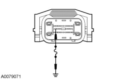
- Ignition ON.
- Observe the ABS warning indicator.
- Does the ABS warning indicator turn off?
Yes
GO to L8.
No
GO to L6.
-------------------------------------------------
L6 CHECK CIRCUIT CCA01 (BU/OG) FOR AN OPEN
- Ignition OFF.
- Disconnect: IC C220b.
- Measure the resistance between the IC C220b-18, circuit CCA01 (BU/OG), harness side and the ABS module C135-17, circuit CCA01 (BU/OG), harness side.
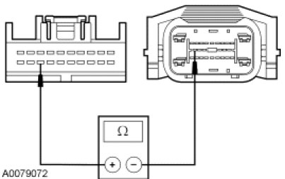
- Is the resistance less than 5 ohms?
Yes
GO to L9.
No
REPAIR the circuit. TEST the system for normal operation.
-------------------------------------------------
L7 CHECK CIRCUIT CCA01 (BU/OG) FOR A SHORT TO GROUND
- Ignition OFF.
- Disconnect: ABS Module C135.
- Disconnect: IC C220b.
- Measure the resistance between the IC C220b-18, circuit CCA01 (BU/OG), harness side and ground.
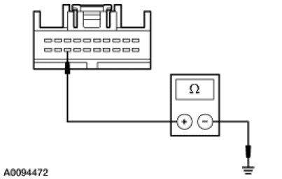
- Is the resistance greater than 10,000 ohms?
Yes
GO to L8.
No
REPAIR the circuit. TEST the system for normal operation.
-------------------------------------------------
L8 CHECK FOR CORRECT ABS MODULE OPERATION
- Disconnect all the ABS module connectors.
- Check for:
- corrosion
- damaged pins
- pushed-out pins
- Connect all the ABS module connectors and make sure they seat correctly.
- Operate the system and verify the concern is still present.
- Is the concern still present?
Yes
INSTALL a new ABS module. TEST the system for normal operation.
No
The system is operating correctly at this time. The concern may have been caused by a loose or corroded connector.
-------------------------------------------------
L9 CHECK FOR CORRECT IC OPERATION
- Disconnect all the IC connectors.
- Check for:
- corrosion
- damaged pins
- pushed-out pins
- Connect all the IC connectors and make sure they seat correctly.
- Operate the system and verify the concern is still present.
- Is the concern still present?
Yes
INSTALL a new IC. REFER to Instrument Cluster (IC) Instrument Cluster (IC). TEST the system for normal operation.
No
The system is operating correctly at this time. The concern may have been caused by a loose or corroded connector.
-------------------------------------------------