Wide Angle Front: Removal
 Courtesy of VOLVO CARS CORPORATION
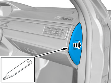
Remove the panel.
 Courtesy of VOLVO CARS CORPORATION
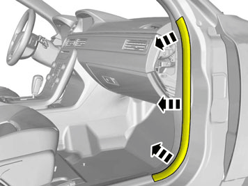
Remove the panel.
 Courtesy of VOLVO CARS CORPORATION
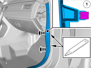
Remove the weatherstrip.
 Courtesy of VOLVO CARS CORPORATION
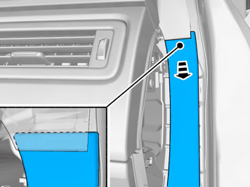
Remove the panel.
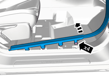 Courtesy of VOLVO CARS CORPORATION
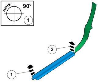 Courtesy of VOLVO CARS CORPORATION
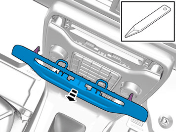 Courtesy of VOLVO CARS CORPORATION
Remove the panel.
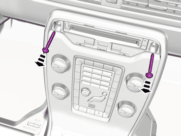 Courtesy of VOLVO CARS CORPORATION
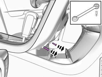
Remove the screws.
 Courtesy of VOLVO CARS CORPORATION
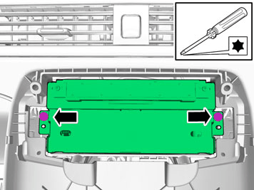
Remove the screws.
 Courtesy of VOLVO CARS CORPORATION
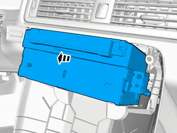
Remove the screws.
 Courtesy of VOLVO CARS CORPORATION
 Courtesy of VOLVO CARS CORPORATION
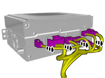
CAUTION:
The number of connectors can vary depending on the vehicle's equipment level.
Disconnect the connectors.
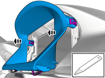 Courtesy of VOLVO CARS CORPORATION
Remove the panel.
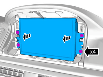 Courtesy of VOLVO CARS CORPORATION
Remove the screws.
Remove the panel.
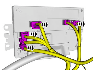 Courtesy of VOLVO CARS CORPORATION
CAUTION:
The number of connectors can vary depending on the vehicle's equipment level.
Disconnect the connectors.
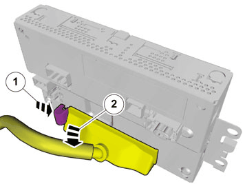 Courtesy of VOLVO CARS CORPORATION
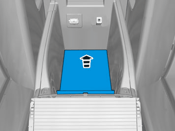 Courtesy of VOLVO CARS CORPORATION
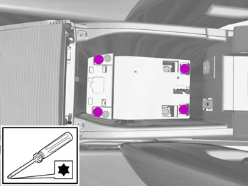 Courtesy of VOLVO CARS CORPORATION
Remove the screws.
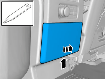 Courtesy of VOLVO CARS CORPORATION
Remove the panel.
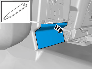 Courtesy of VOLVO CARS CORPORATION
Remove the panel.
 Courtesy of VOLVO CARS CORPORATION
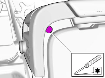
Remove the screws.
On both sides.
 Courtesy of VOLVO CARS CORPORATION
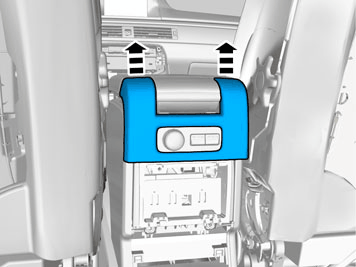
Remove the panel.
 Courtesy of VOLVO CARS CORPORATION
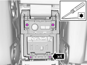
Remove the screws.
 Courtesy of VOLVO CARS CORPORATION
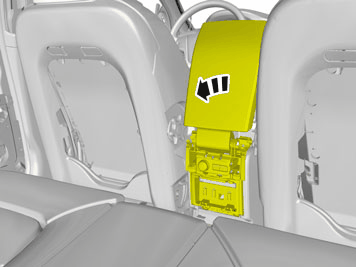
Detach the panel.
 Courtesy of VOLVO CARS CORPORATION
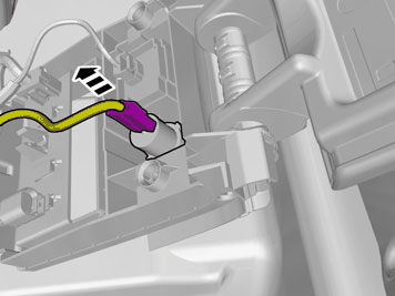
Disconnect the connector.
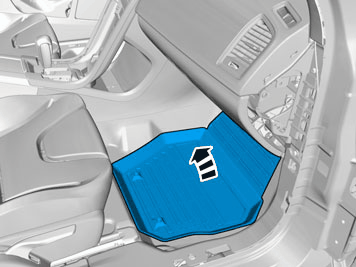 Courtesy of VOLVO CARS CORPORATION
 Courtesy of VOLVO CARS CORPORATION
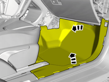
Fold the carpet to the side.
 Courtesy of VOLVO CARS CORPORATION
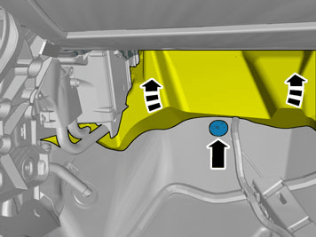
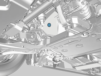
Locate the rubber grommet under the insulation and press it out.
 Courtesy of VOLVO CARS CORPORATION
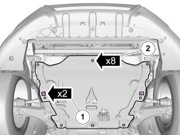
Remove the screws.
Remove the clips.
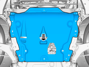 Courtesy of VOLVO CARS CORPORATION
 Courtesy of VOLVO CARS CORPORATION
NOTE:
On some markets the rubber grommet may be covered by the heat shield.
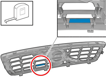 Courtesy of VOLVO CARS CORPORATION
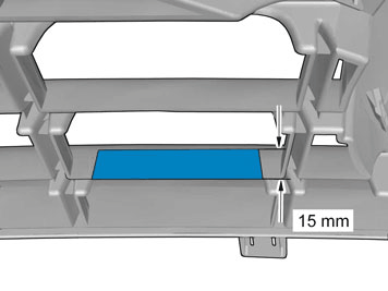 Courtesy of VOLVO CARS CORPORATION
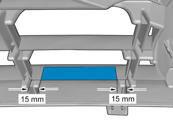 Courtesy of VOLVO CARS CORPORATION
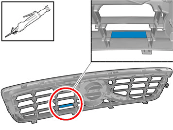 Courtesy of VOLVO CARS CORPORATION