DTC 112: Motor No. 1 Signal High
- This DTC will set if voltage from motor No. 1 potentiometer to seat control module circuit V1 is more than 4.6 volts. To correct this problem, turn ignition off. Using scan tool, select scrolling values and read value for motor No. 1 potentiometer.
- Move seat fully forward and fully backward several times. If voltage does not exceed 4.6 volts, problem is intermittent. Retest system. If voltage exceeds 4.6 volts, go to next step.
- Turn ignition off. Remove seat from vehicle. See POWER SEAT
under REMOVAL & INSTALLATION. Disconnect seat control module 14-pin Black connector. See Fig 1
. Measure resistance between 14-pin Black harness connector terminals No. 12 and 13. See Fig 2
. If resistance is about 2200 ohms, go to step 6
. If resistance is not about 2200 ohms, go to next step.
- Disconnect motor No. 1 potentiometer connector and remove potentiometer. Measure resistance between outside terminals of potentiometer. If resistance is about 2200 ohms, go to next step. If resistance is not about 2200 ohms, replace motor No. 1 potentiometer. See SEAT MOTORS
under REMOVAL & INSTALLATION.
- Measure resistance of Brown wire between seat control module 14-pin Black connector terminal No. 12 and 3-pin motor No. 1 potentiometer connector. If resistance is zero ohms, check and repair connectors for corroded or bent terminals. If resistance is more than zero ohms, repair open in Brown wire.
- Measure resistance between seat control module 14-pin Black connector terminal No. 13 and terminals No. 1-6. See WIRING DIAGRAMS
. Measure resistance between seat control module 14-pin Black connector terminal No. 9 and terminals No. 1-6. If resistance of all measurements is infinite, potentiometer and wiring are okay. Check seat control module 14-pin Black connector for corroded or bent terminals. If connector and terminals are okay, replace seat control module. See SEAT CONTROL MODULE
under REMOVAL & INSTALLATION. If resistance of all measurements is not infinite, repair short in Red wire between seat control module 14-pin Black connector terminal No. 13 and potentiometer or Yellow/Red wire between seat control module 14-pin Black connector terminal No. 9 and potentiometer. Retest system.
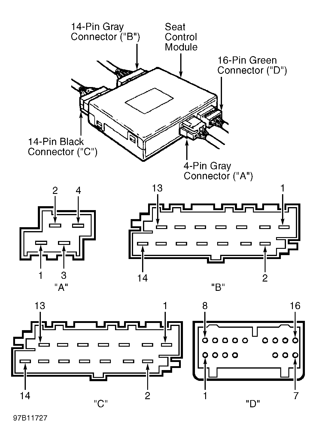 Courtesy of VOLVO CARS OF NORTH AMERICA
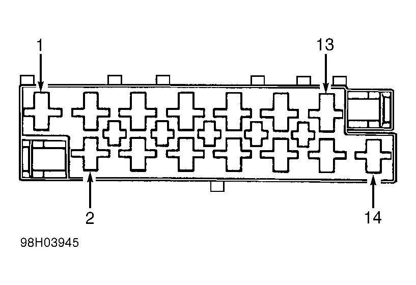 Courtesy of VOLVO CARS OF NORTH AMERICA