S90 & V90
- Ensure temperature gauge operates properly, as fuel gauge receives current from temperature gauge. If temperature gauge does not operate correctly, go to TEMPERATURE GAUGE TEST .
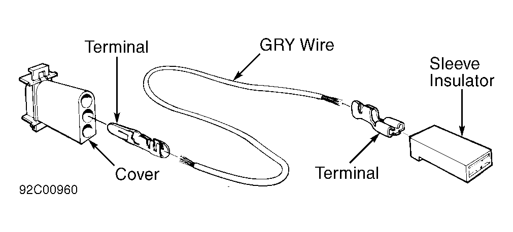
- If temperature gauge is okay, fuel gauge can be checked with a 68-Ohm Test Resistor (999-5824-1). Assemble an adapter from the following components. See Fig 1.
- Gray Wire (954-441)
- Terminal (948-291)
- Terminal (942-201)
- Sleeve Insulator (948-296)
- Cover (943511)
 Courtesy of VOLVO CARS OF NORTH AMERICA.
- Disconnect Gray/White wire from fuel tank sending unit. Connect test resistor between ground and disconnected wire. If gauge is okay, it should indicate 1/4 full (15-gallon tank) or 1/5 full (21-gallon tank). If gauge operates as specified, sending unit is defective.
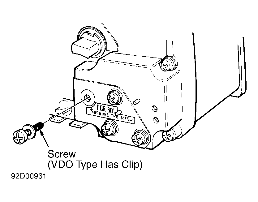
- If needle is not on specified section, ensure gauge is set for 15-gallon or 21-gallon tank. Yazaki gauges use a screw and VDO gauges use a clip, if equipped with a 15-gallon tank. See Fig 2. Clip or screw should be removed for 21-gallon tank.
 Courtesy of VOLVO CARS OF NORTH AMERICA.
- If gauge is correctly set, but still gives incorrect reading, sending unit is probably defective. If needle does not move at all, check continuity of wiring to gauge. If wiring is okay, gauge should be replaced.
- If fuel gauge replacement is necessary, check rear side of instrument panel to see if a potentiometer has been installed. If so, gauge will require adjustment.
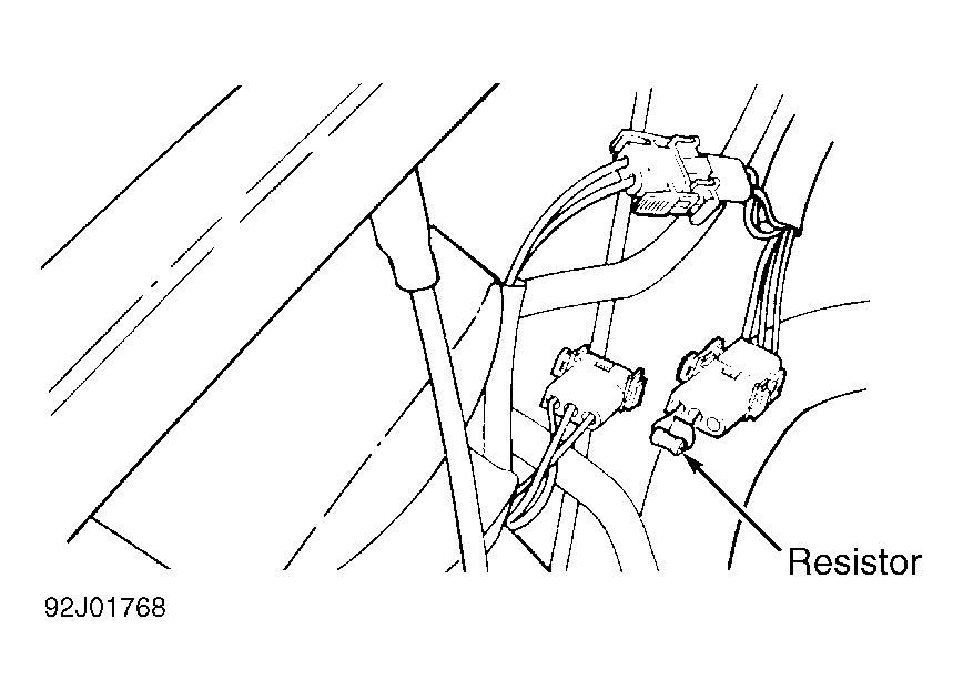
- If not already present, Fuel Gauge Potentiometer Kit (1-398-171-7) will need to be installed in order to adjust fuel gauge. Disconnect negative battery cable. Disconnect fuel gauge sending unit connector and install resistor to gauge side of wiring. See Fig 3.
 Courtesy of VOLVO CARS OF NORTH AMERICA.
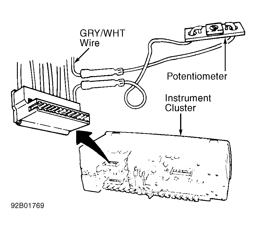
- Cut Gray/White wire next to 7-pin connector on instrument panel. Using sleeve insulators, join both sides to potentiometer. See Fig 4. Reconnect negative battery cable. Turn ignition on with engine off. If needle on fuel gauge just touches Red section, go to step 10. If not, go to next step.
 Courtesy of VOLVO CARS OF NORTH AMERICA.
- Turn ignition off. Disconnect negative battery cable. Using a screwdriver, adjust potentiometer. Initial adjustment is 33 ohms. Reduce by turning screw clockwise until correct needle deflection is obtained.
- With negative battery cable still disconnected, seal potentiometer with a drop of paint. Wrap electrical tape around potentiometer to prevent short circuits. Remove test resistor and reconnect wiring. Reconnect negative battery cable.