Hydraulic System Overview
WARNING: This page is about a different car, the 2016 Volkswagen Beetle, 2015 Volkswagen Beetle, 2014 Volkswagen Beetle, and 2013 Volkswagen Beetle. However, it is still accessible from the selected car via links, so may be relevant.
 Courtesy of VOLKSWAGEN GROUP OF AMERICA, INC.
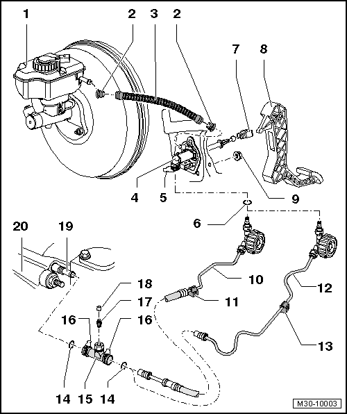
- Brake Fluid Reservoir
- Gasket
- For the plastic supply hose.
- The seals must be inside the supply hose.
- Supply Hose
- To the brake fluid reservoir.
- Plastic, with additional seals. Refer to Fig 3.
- Clutch Master Cylinder
- Clip
- To remove and install the hose/line assembly or line, pull the clip all the way out.
- On some clutch master cylinders, it is pulled out on the side.
- Seal/O-Ring
- Installed on the line connection.
- Install using brake fluid.
- Seal or O-ring suitable for the hose/line connection, refer to Fig 2.
- Grease allocation.
- Mounting
- To remove and install, disconnect the clutch master cylinder from the clutch pedal. Refer to CLUTCH PEDAL .
- Clutch Pedal
- Nut
- Tightening specification. Refer to CLUTCH PEDAL OVERVIEW .
- Always replace after removing.
- Self-locking
- Quantity: 3
- For the mounting bracket to the bulkhead.
- Hose/Line Assembly
- Bracket
- For the hose/line assembly -item 10-.
- Attached to the body.
- Covered by the assembly mounting.
- Bracket differentiation, refer to Fig 4.
- Line
- Bracket
- For the line -item 12-.
- Attached to the body.
- Covered by the assembly mounting.
- Bracket differentiation, refer to Fig 4.
- Seal or O-ring
- Installed on the line connection.
- Install using brake fluid.
- Seal or O-ring suitable for the line connection, refer to Fig 2.
- Grease allocation.
- Bleeder Assembly
- Clip
- To remove and install the hose/line assembly or line and bleeder, pull the clip all the way out.
- Bleed Valve
- Dust Cap
- Clutch Slave Cylinder
- Transmission
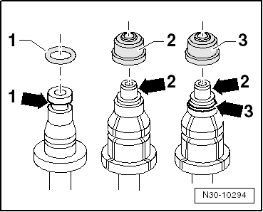 Courtesy of VOLKSWAGEN GROUP OF AMERICA, INC.
| Item |
Line Connection Version |
| 1 |
Line connection with a groove all the way around -arrow 1- |
| 2 |
Line connection with a shoulder -arrow 2- |
| 3 |
Line connection with a shoulder -arrow 2- and with a groove all the way around -arrow 3- |
- The seal/O-ring must be installed in the groove -arrows 1- and -arrow 3-.
 Courtesy of VOLKSWAGEN GROUP OF AMERICA, INC.
- The seals -2- must be inside the plastic supply hose -1-.
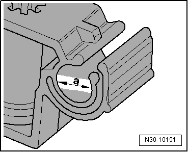 Courtesy of VOLKSWAGEN GROUP OF AMERICA, INC.
| Dimension -a- |
Line Version |
| 8 mm |
Line |
| 6 mm |
Hose/Line Assembly |