Caution / Notice / Hint
WARNING: This page is about a different variant/trim than selected.
COMPONENTS (REMOVAL)
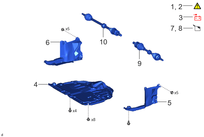 Courtesy of © TOYOTA, LICENSE AGREEMENT TMS1002
| Procedure |
Part Name Code |
 Courtesy of © TOYOTA, LICENSE AGREEMENT TMS1002 Courtesy of © TOYOTA, LICENSE AGREEMENT TMS1002
|
 |
 |
| 1 |
PRECAUTION |
- |
See step 1 |
- |
- |
| 2 |
ALIGN FRONT WHEELS FACING STRAIGHT AHEAD |
- |
See step 2 |
- |
- |
| 3 |
DISCONNECT CABLE FROM NEGATIVE AUXILIARY BATTERY TERMINAL |
- |
- |
- |
- |
| 4 |
NO. 1 ENGINE UNDER COVER ASSEMBLY |
51410 |
- |
- |
- |
| 5 |
REAR ENGINE UNDER COVER LH |
51444A |
- |
- |
- |
| 6 |
REAR ENGINE UNDER COVER RH |
51443C |
- |
- |
- |
| 7 |
DRAIN ENGINE COOLANT |
- |
- |
See step 7 |
- |
| 8 |
DRAIN CONTINUOUSLY VARIABLE TRANSAXLE FLUID |
- |
- |
See step 8 |
- |
| 9 |
FRONT DRIVE SHAFT ASSEMBLY LH |
43420 |
- |
- |
- |
| 10 |
FRONT DRIVE SHAFT ASSEMBLY RH |
43410 |
- |
- |
- |
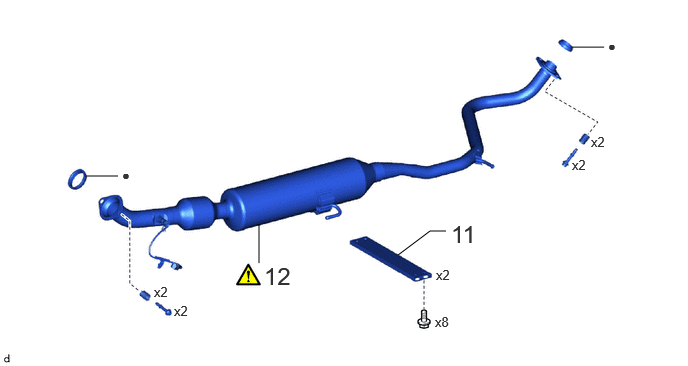 Courtesy of © TOYOTA, LICENSE AGREEMENT TMS1002
| Procedure |
Part Name Code |
Courtesy of © TOYOTA, LICENSE AGREEMENT TMS1002
|
|
|
| 11 |
FRONT FLOOR CENTER BRACE |
57533B |
- |
- |
- |
| 12 |
FRONT EXHAUST PIPE ASSEMBLY (TWC: Rear Catalyst) |
17410 |
See step 12 |
- |
- |
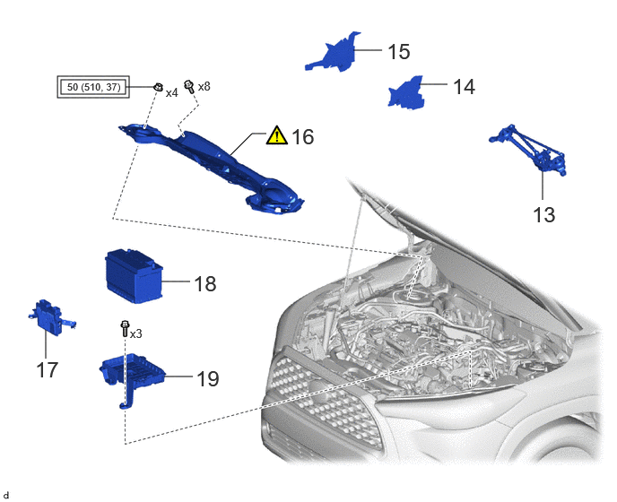
 Courtesy of © TOYOTA, LICENSE AGREEMENT TMS1002© TOYOTA, LICENSE AGREEMENT TMS1002
| Callout - Procedure |
Part Name Code |
Courtesy of © TOYOTA, LICENSE AGREEMENT TMS1002
|
|
|
| 13 |
WINDSHIELD WIPER MOTOR AND LINK ASSEMBLY |
- |
- |
- |
- |
| 14 |
WATER GUARD PLATE |
55734D |
- |
- |
- |
| 15 |
NO. 1 HEATER AIR DUCT SPLASH SHIELD SEAL |
55737B |
- |
- |
- |
| 16 |
OUTER COWL TOP PANEL SUB-ASSEMBLY |
55701J |
See step 16 |
- |
- |
| 17 |
ECM |
89661 |
- |
- |
- |
| 18 |
AUXILIARY BATTERY |
- |
- |
- |
- |
| 19 |
BATTERY CLAMP SUB-ASSEMBLY |
74404A |
- |
- |
- |
|
Tightening torque for "Major areas involving basic vehicle performance such as moving/turning/stopping": N.m (kgf/cm, ft.lbf) |
- |
- |
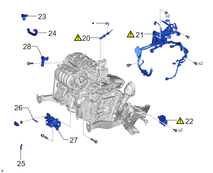 Courtesy of © TOYOTA, LICENSE AGREEMENT TMS1002
| Procedure |
Part Name Code |
Courtesy of © TOYOTA, LICENSE AGREEMENT TMS1002
|
|
|
| 20 |
TRANSMISSION CONTROL CABLE ASSEMBLY |
33820B |
See step 20 |
- |
- |
| 21 |
DISCONNECT ENGINE WIRE |
82121 |
See step 21 |
- |
- |
| 22 |
TCM |
89535B |
See step 22 |
- |
- |
| 23 |
INLET WATER HOSE |
16262 |
- |
- |
- |
| 24 |
NO. 2 WATER BY-PASS HOSE |
16264D |
- |
- |
- |
| 25 |
FLYWHEEL HOUSING SIDE COVER |
11363A |
- |
- |
- |
| 26 |
DISCONNECT ENGINE WIRE |
82121 |
- |
- |
- |
| 27 |
STARTER ASSEMBLY |
28100 |
- |
- |
- |
| 28 |
FUEL DELIVERY GUARD |
23825 |
- |
- |
- |
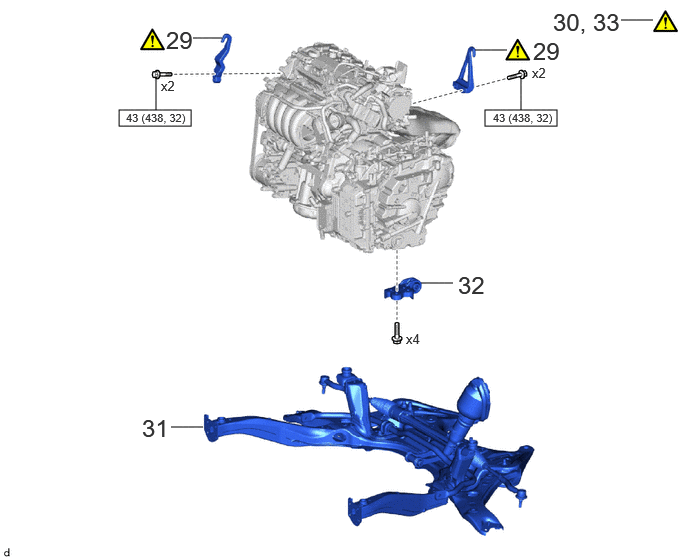
 Courtesy of © TOYOTA, LICENSE AGREEMENT TMS1002© TOYOTA, LICENSE AGREEMENT TMS1002
| Callout - Procedure |
Part Name Code |
Courtesy of © TOYOTA, LICENSE AGREEMENT TMS1002
|
|
|
| 29 |
ENGINE HANGER |
- |
See step 29 |
- |
- |
| 30 |
ENGINE SUPPORT BRIDGE |
- |
See step 30 |
- |
- |
| 31 |
FRONT SUSPENSION CROSSMEMBER SUB-ASSEMBLY |
51201F |
- |
- |
- |
| 32 |
NO. 2 ENGINE MOVING CONTROL ROD |
12364B |
- |
- |
- |
| 33 |
SUPPORT TRANSAXLE ASSEMBLY |
- |
See step 33 |
- |
- |
|
N.m (kgf/cm, ft.lbf): Specified torque |
- |
- |
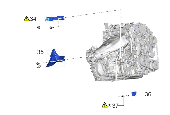 Courtesy of © TOYOTA, LICENSE AGREEMENT TMS1002
| Procedure |
Part Name Code |
Courtesy of © TOYOTA, LICENSE AGREEMENT TMS1002
|
|
|
| 34 |
MANIFOLD STAY |
17118 |
See step 34 |
- |
- |
| 35 |
DRIVE SHAFT HEAT INSULATOR SUB-ASSEMBLY |
43409E |
- |
- |
- |
| 36 |
FLYWHEEL HOUSING UNDER COVER |
11361J |
- |
- |
- |
| 37 |
DRIVE PLATE AND TORQUE CONVERTER ASSEMBLY SETTING BOLT |
32101G |
See step 37 |
- |
- |
| *a |
Black Color: x1
Silver Color: x5 |
- |
- |
| * |
Precoated part |
- |
- |
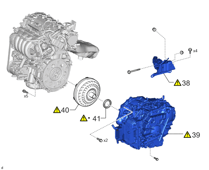 Courtesy of © TOYOTA, LICENSE AGREEMENT TMS1002
| Procedure |
Part Name Code |
Courtesy of © TOYOTA, LICENSE AGREEMENT TMS1002
|
|
|
| 38 |
ENGINE MOUNTING INSULATOR LH |
12372A |
See step 38 |
- |
- |
| 39 |
CONTINUOUSLY VARIABLE TRANSAXLE ASSEMBLY |
30400 |
See step 39 |
- |
- |
| 40 |
TORQUE CONVERTER ASSEMBLY |
32000A |
See step 40 |
- |
- |
| 41 |
TRANSAXLE HOUSING TYPE T OIL SEAL |
30400E |
See step 41 |
- |
- |
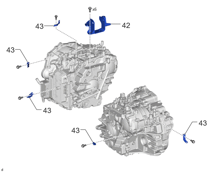 Courtesy of © TOYOTA, LICENSE AGREEMENT TMS1002
| Procedure |
Part Name Code |
Courtesy of © TOYOTA, LICENSE AGREEMENT TMS1002
|
|
|
| 42 |
ENGINE MOUNTING BRACKET LH |
12325A |
- |
- |
- |
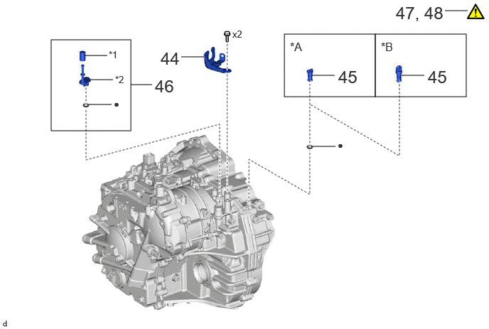
| 43 |
WIRE HARNESS CLAMP BRACKET |
- |
- |
- |
- |
 Courtesy of © TOYOTA, LICENSE AGREEMENT TMS1002
| Procedure |
Part Name Code |
Courtesy of © TOYOTA, LICENSE AGREEMENT TMS1002
|
|
|
| 44 |
NO. 1 TRANSMISSION CONTROL CABLE BRACKET |
33823 |
- |
- |
- |
| 45 |
TRANSMISSION CASE PLUG ASSEMBLY |
35150B |
- |
- |
- |
| 46 |
BREATHER PLUG SUB-ASSEMBLY |
- |
- |
- |
- |
| 47 |
INSPECT TORQUE CONVERTER ASSEMBLY |
- |
See step 47 |
- |
- |
| 48 |
INSPECT DRIVE PLATE AND RING GEAR SUB-ASSEMBLY |
- |
See step 48 |
- |
- |
| *A |
for Type A |
*B |
for Type B |
| *1 |
BREATHER PLUG CAP |
*2 |
BREATHER PLUG |
| • |
Non-reusable part |
- |
- |
The necessary procedures (adjustment, calibration, initialization, or registration) that must be performed after parts are removed and installed, or replaced during the continuously variable transaxle assembly removal/installation are shown below.
NECESSARY PROCEDURES AFTER PARTS REMOVED/INSTALLED/REPLACED
| Replacement Part or Procedure |
Necessary Procedures |
Effect/Inoperative Function When Necessary Procedures are not Performed |
Link |
| Continuously variable transaxle assembly |
- Reset memory
- Transaxle compensation code (Input or Initialize)
- CVT oil pressure calibration
|
Deterioration of fuel efficiency |
for Initialization:
Refer to INITIALIZATION [11/2022 - 11/2023]
for Registration:
Refer to REGISTRATION [09/2021 - 11/2023] |
| CVT fluid |
ATF thermal degradation estimate reset |
The value of the Data List item "ATF Thermal Degradation Estimate" is not estimated correctly |
Refer to INITIALIZATION [11/2022 - 11/2023] |
| Bleed air from oil pump (continuously variable transaxle assembly) |
Stop and start system |
Refer to REGISTRATION [09/2021 - ] |
| Front wheel alignment adjustment |
- Perform "Reset Memory"
- Perform "Calibration"
|
- DTCs are stored
- ABS warning light illuminates
- Slip indicator light illuminates
- Electronically controlled brake system does not operate correctly
|
Refer to UTILITY [11/2022 - ] |
| No. 2 steering intermediate shaft assembly |
End position initial setting |
Power steering system |
Refer to END POSITION INITIAL SETTING [11/2022 - ] |
| Suspension, tires, etc. |
Rear television camera assembly optical axis (Back camera position setting) |
Parking assist monitor system |
Refer to CALIBRATION [11/2022 - ] |
| Initialize headlight ECU sub-assembly LH |
Automatic headlight beam level control system |
Refer to INITIALIZATION [11/2022 - ] |
WARNING:
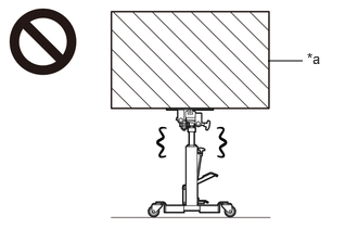
- Because the continuously variable transaxle assembly is extremely heavy, make sure to follow the work procedures described in the appropriate service information
.
 Courtesy of © TOYOTA, LICENSE AGREEMENT TMS1002 Courtesy of © TOYOTA, LICENSE AGREEMENT TMS1002
|
| *a |
Heavy object exceeding the capacity of the transmission jack |
- If work is not performed according to the procedures described in the appropriate service information
, there is a danger that the transmission jack could drop and components could fall down.
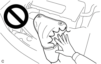
- When the engine is hot, do not touch high-temperature areas such as the engine or exhaust manifold.
 Courtesy of © TOYOTA, LICENSE AGREEMENT TMS1002 Courtesy of © TOYOTA, LICENSE AGREEMENT TMS1002
|
- Touching high-temperature areas such as the engine and exhaust manifold could result in burns.
HINT:
When the cable is disconnected / reconnected to the auxiliary battery terminal, systems temporarily stop operating. However, each system has a function that completes learning the first time the system is used.
- Learning completes when vehicle is driven
| Effect/Inoperative Function When Necessary Procedures are not Performed |
Necessary Procedures |
Link |
| Front camera system |
Drive the vehicle straight ahead at 15 km/h (10 mph) or more for 1 second or more. |
Refer to INITIALIZATION [11/2022 - ] |
| Stop and start system |
Drive the vehicle until stop and start control is permitted (approximately 5 to 60 minutes) |
Refer to PRECAUTION [11/2022 - 11/2023] |
- Learning completes when vehicle is operated normally
| Effect/Inoperative Function When Necessary Procedures are not Performed |
Necessary Procedures |
Link |
| Power door lock control system
|
Perform door unlock operation with door control switch or electrical key transmitter sub-assembly switch. |
Refer to INITIALIZATION [11/2022 - ] |
| Power back door system |
Fully close the back door by hand.
HINT:
Initialization is not necessary if the above procedures are performed while the back door is closed. |
Refer to INITIALIZATION [09/2021 - ] |
| Air conditioning system |
After the ignition switch is turned to ON, the servo motor standard position is recognized. |
- |