Caution / Notice / Hint
WARNING: This page is about a different car, the 2025 Toyota Corolla Cross, 2024 Toyota Corolla Cross, and 2023 Toyota Corolla Cross. However, it is still accessible from the selected car via links, so may be relevant.
The necessary procedures (adjustment, calibration, initialization or registration) that must be performed after parts are removed, installed, or replaced during the engine assembly removal/installation are shown below.
NECESSARY PROCEDURES AFTER PARTS REMOVED/INSTALLED/REPLACED
| Replaced Part or Performed Procedure |
Necessary Procedure |
Effect/Inoperative Function when Necessary Procedure not Performed |
Link |
- Replacement of engine assembly
- Gas leaks from exhaust system is repaired
|
Inspection After Repair |
- Poor idle, etc.
- Engine start function, etc.
|
Refer to INITIALIZATION [11/2022 - ] |
| Replacement of inverter with converter assembly |
Resolver learning |
- DTCs are stored
- Slight vibration at a vehicle speed of 5 km/h (3 mph) or less
- Shock or vibration during acceleration
|
Refer to UTILITY [11/2022 - ] |
| Replacement of hybrid vehicle transaxle assembly |
- Resolver learning
- Initialize resolver
|
| Front wheel alignment adjustment |
Perform "Calibration" |
- DTCs are stored
- ABS warning light illuminates
- Brake system warning light (yellow indicator) illuminates
- Slip indicator light illuminates
- Electronically controlled brake system does not operate correctly
|
Refer to UTILITY [11/2022 - ] |
| Suspension, tires, etc. |
Rear television camera assembly optical axis (Back camera position setting) |
Parking Assist Monitor System |
Refer to CALIBRATION [11/2022 - ] |
| Initialize headlight ECU subassembly LH |
Automatic headlight beam level control system |
Refer to INITIALIZATION [11/2022 - ] |
WARNING:
- The engine assembly with transaxle is very heavy. Be sure to follow the procedure described in the service information, or the engine lifter may suddenly drop or the engine assembly with transaxle may fall off the engine lifter.
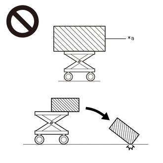 Courtesy of © TOYOTA, LICENSE AGREEMENT TMS1002
| *a |
An Object Exceeding Weight Limit of Engine Lifter |
- To prevent burns, do not touch the engine, exhaust manifold or other high temperature components while the engine is hot.
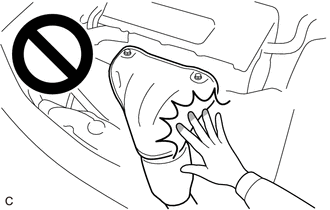 Courtesy of © TOYOTA, LICENSE AGREEMENT TMS1002
HINT:
When the cable is disconnected/reconnected to the auxiliary battery terminal, systems temporarily stop operating. However, each system has a function that completes learning the first time the system is used.
- Learning completes when vehicle is driven
| Effect/Inoperative Function When Necessary Procedures are not Performed |
Necessary Procedures |
Link |
| Front Camera System |
Drive the vehicle straight ahead at 15 km/h (10 mph) or more for 1 second or more. |
Refer to INITIALIZATION [11/2022 - ] |
- Learning completes when vehicle is operated normally
| Effect/Inoperative Function When Necessary Procedures are not Performed |
Necessary Procedures |
Link |
| Power door lock control system
|
Perform door unlock operation with door control switch or electrical key transmitter sub-assembly switch. |
Refer to INITIALIZATION [11/2022 - ] |
| Power back door system |
Fully close the back door by hand.
HINT:
Initialization is not necessary if the above procedures are performed while the back door is closed. |
Refer to INITIALIZATION [09/2021 - ] |
| Air conditioning system |
After the ignition switch is turned to ON, the servo motor standard position is recognized. |
- |
COMPONENTS (REMOVAL)
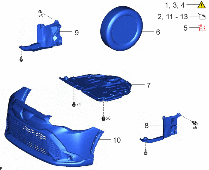 Courtesy of © TOYOTA, LICENSE AGREEMENT TMS1002
| Procedure |
Part Name Code |
 Courtesy of © TOYOTA, LICENSE AGREEMENT TMS1002 Courtesy of © TOYOTA, LICENSE AGREEMENT TMS1002
|
 |
 |
| 1 |
PRECAUTION |
- |
See step 1 |
- |
- |
| 2 |
RECOVER REFRIGERANT FROM REFRIGERATION SYSTEM |
- |
- |
See step 2 |
- |
| 3 |
DISCHARGE FUEL SYSTEM PRESSURE |
- |
See step 3 |
- |
- |
| 4 |
ALIGN FRONT WHEELS FACING STRAIGHT AHEAD |
- |
See step 4 |
- |
- |
| 5 |
DISCONNECT CABLE FROM NEGATIVE AUXILIARY BATTERY TERMINAL |
- |
- |
- |
- |
| 6 |
FRONT WHEELS |
- |
See step 6 |
- |
- |
| 7 |
NO. 1 ENGINE UNDER COVER ASSEMBLY |
51410 |
- |
- |
- |
| 8 |
REAR ENGINE UNDER COVER LH |
51444A |
- |
- |
- |
| 9 |
REAR ENGINE UNDER COVER RH |
51443C |
- |
- |
- |
| 10 |
FRONT BUMPER ASSEMBLY |
- |
- |
- |
- |
| 11 |
DRAIN ENGINE OIL |
- |
- |
See step 11 |
- |
| 12 |
DRAIN ENGINE COOLANT |
- |
- |
See step 12 |
- |
| 13 |
DRAIN HYBRID TRANSAXLE FLUID |
- |
- |
See step 13 |
- |
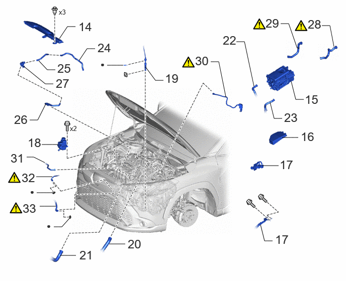 Courtesy of © TOYOTA, LICENSE AGREEMENT TMS1002
| Procedure |
Part Name Code |
Courtesy of © TOYOTA, LICENSE AGREEMENT TMS1002
|
|
|
| 14 |
INLET NO. 1 AIR CLEANER |
17751 |
- |
- |
- |
| 15 |
INVERTER WITH CONVERTER ASSEMBLY |
G92A0 |
- |
- |
- |
| 16 |
NO. 1 RELAY BLOCK COVER |
82662A |
- |
- |
- |
| 17 |
DISCONNECT ENGINE WIRE |
- |
- |
- |
- |
| 18 |
INVERTER RESERVE TANK ASSEMBLY |
G92A0A |
- |
- |
- |
| 19 |
TRANSMISSION CONTROL CABLE ASSEMBLY |
33820B |
- |
- |
- |
| 20 |
NO. 1 RADIATOR HOSE |
16571C |
- |
- |
- |
| 21 |
NO. 2 RADIATOR HOSE |
16572D |
- |
- |
- |
| 22 |
INLET HYBRID RADIATOR HOSE |
G922H |
- |
- |
- |
| 23 |
OUTLET NO. 1 HYBRID WATER PUMP HOSE |
G922C |
- |
- |
- |
| 24 |
NO. 3 FUEL VAPOR FEED HOSE |
23827F |
- |
- |
- |
| 25 |
FUEL VAPOR FEED HOSE NO. 2 |
23827A |
- |
- |
- |
| 26 |
FUEL VAPOR FEED HOSE NO. 1 |
23826 |
- |
- |
- |
| 27 |
PURGE VALVE (PURGE VSV) |
25860 |
- |
- |
- |
| 28 |
INLET HEATER WATER HOSE |
- |
See step 28 |
- |
- |
| 29 |
OUTLET HEATER WATER HOSE |
- |
See step 29 |
- |
- |
| 30 |
FUEL TUBE SUB-ASSEMBLY |
23901 |
See step 30 |
- |
- |
| 31 |
WATER BY-PASS HOSE |
16283B |
- |
- |
- |
| 32 |
DISCHARGE HOSE SUB-ASSEMBLY |
88703 |
See step 32 |
- |
- |
| 33 |
SUCTION HOSE SUB-ASSEMBLY |
88704 |
See step 33 |
- |
- |
 Courtesy of © TOYOTA, LICENSE AGREEMENT TMS1002
| Procedure |
Part Name Code |
Courtesy of © TOYOTA, LICENSE AGREEMENT TMS1002
|
|
|
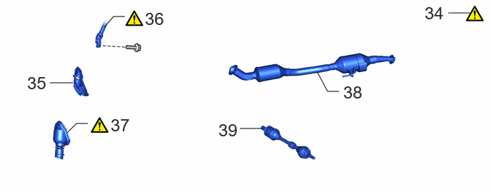
| 34 |
SECURE STEERING WHEEL |
- |
See step 34 |
- |
- |
| 35 |
COLUMN HOLE COVER SILENCER SHEET |
45259A |
- |
- |
- |
| 36 |
NO. 2 STEERING INTERMEDIATE SHAFT ASSEMBLY |
45260 |
See step 36 |
- |
- |
| 37 |
NO. 1 STEERING COLUMN HOLE COVER SUB-ASSEMBLY |
45025D |
See step 37 |
- |
- |
| 38 |
FRONT EXHAUST PIPE ASSEMBLY |
17410 |
- |
- |
- |
| 39 |
DRIVE SHAFT ASSEMBLY |
- |
- |
- |
- |
 Courtesy of © TOYOTA, LICENSE AGREEMENT TMS1002
| Procedure |
Part Name Code |
Courtesy of © TOYOTA, LICENSE AGREEMENT TMS1002
|
|
|
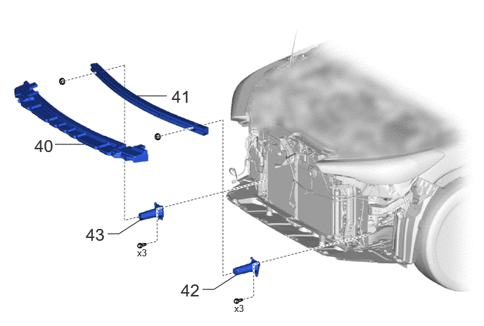
| 40 |
FRONT BUMPER LOWER ABSORBER |
52618 |
- |
- |
- |
| 41 |
NO. 2 FRONT BUMPER REINFORCEMENT |
52132A |
- |
- |
- |
| 42 |
FRONT BUMPER BAR REINFORCEMENT LH |
52134C |
- |
- |
- |
| 43 |
FRONT BUMPER BAR REINFORCEMENT RH |
52133C |
- |
- |
- |
 Courtesy of © TOYOTA, LICENSE AGREEMENT TMS1002© TOYOTA, LICENSE AGREEMENT TMS1002
| Callout - Procedure |
Part Name Code |
Courtesy of © TOYOTA, LICENSE AGREEMENT TMS1002
|
|
|
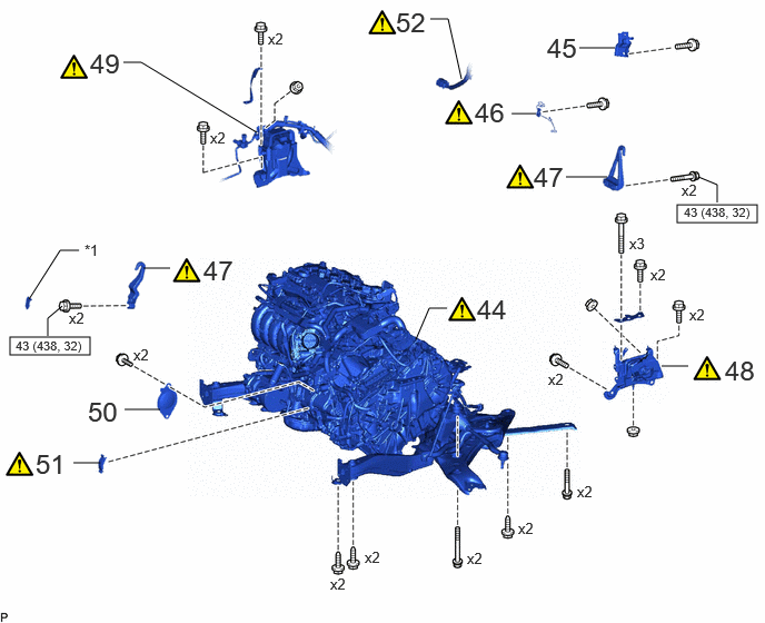
| 44 |
ENGINE ASSEMBLY WITH TRANSAXLE |
- |
See step 44 |
- |
- |
| 45 |
EMISSION CONTROL VALVE BRACKET |
- |
- |
- |
- |
| 46 |
WIRE HARNESS CLAMP BRACKET |
- |
See step 46 |
- |
- |
| 47 |
ENGINE HANGERS |
- |
See step 47 |
- |
- |
| 48 |
ENGINE MOUNTING INSULATOR LH |
12372A |
See step 48 |
- |
- |
| 49 |
ENGINE MOUNTING INSULATOR SUB-ASSEMBLY RH |
12305 |
See step 49 |
- |
- |
| 50 |
STARTER HOLE INSULATOR |
28193 |
- |
- |
- |
| 51 |
FLYWHEEL HOUSING SIDE COVER |
11363A |
See step 51 |
- |
- |
| 52 |
HV AIR CONDITIONING WIRE |
821H2 |
See step 52 |
- |
- |
| *1 |
ENGINE MOUNTING BRACKET CAP |
|
|
 |
N*m (kgf*cm, ft.*lbf): Specified torque |
- |
- |
 Courtesy of © TOYOTA, LICENSE AGREEMENT TMS1002
| Procedure |
Part Name Code |
Courtesy of © TOYOTA, LICENSE AGREEMENT TMS1002
|
|
|
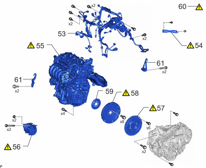
| 53 |
REMOVE ENGINE WIRE |
82121 |
- |
- |
- |
| 54 |
MANIFOLD STAY |
17118 |
See step 54 |
- |
- |
| 55 |
ENGINE ASSEMBLY |
- |
See step 55 |
- |
- |
| 56 |
COMPRESSOR WITH MOTOR ASSEMBLY |
88370 |
See step 56 |
- |
- |
| 57 |
TRANSMISSION INPUT DAMPER ASSEMBLY |
31270 |
See step 57 |
- |
- |
| 58 |
FLYWHEEL SUB-ASSEMBLY |
13405 |
See step 58 |
- |
- |
| 59 |
NO. 1 CRANKSHAFT POSITION SENSOR PLATE |
19315 |
- |
- |
- |
| 60 |
ENGINE TO ENGINE STAND |
- |
See step 60 |
- |
- |
| 61 |
REMOVE ENGINE HANGERS |
- |
- |
- |
- |