Caution / Notice / Hint
COMPONENTS (REMOVAL)
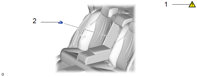 Courtesy of © TOYOTA, LICENSE AGREEMENT TMS1002
| Procedure |
Part Name Code |
 Courtesy of © TOYOTA, LICENSE AGREEMENT TMS1002 Courtesy of © TOYOTA, LICENSE AGREEMENT TMS1002
|
 |
 |
| 1 |
RELEASE PARKING BRAKE |
- |
See step 1 |
- |
- |
| 2 |
SERVICE PLUG GRIP |
G3834 |
- |
- |
- |
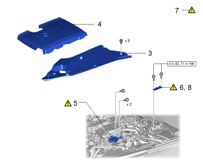 Courtesy of © TOYOTA, LICENSE AGREEMENT TMS1002
| Procedure |
Part Name Code |
Courtesy of © TOYOTA, LICENSE AGREEMENT TMS1002
|
|
|
| 3 |
UPPER RADIATOR SUPPORT SEAL |
53292A |
- |
- |
- |
| 4 |
FC STACK COVER SUB-ASSEMBLY |
1A906 |
- |
- |
- |
| 5 |
FC CONVERTER POWER OUTLET CABLE (INVERTER WITH CONVERTER ASSEMBLY) |
G9200A |
See step 5 |
- |
- |
| 6 |
REMOVE CONNECTOR COVER ASSEMBLY |
- |
See step 6 |
- |
- |
| 7 |
CHECK TERMINAL VOLTAGE |
- |
See step 7 |
- |
- |
| 8 |
INSTALL CONNECTOR COVER ASSEMBLY |
- |
See step 8 |
- |
- |
 |
N.m (kgf/cm, ft.lbf): Specified torque |
- |
- |
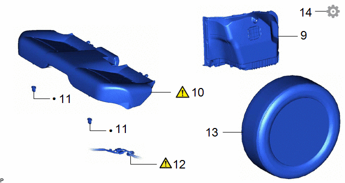 Courtesy of © TOYOTA, LICENSE AGREEMENT TMS1002
| Procedure |
Part Name Code |
Courtesy of © TOYOTA, LICENSE AGREEMENT TMS1002
|
|
|
| 9 |
INNER LUGGAGE COMPARTMENT TRIM COVER LH |
64722 |
- |
- |
- |
| 10 |
BENCH TYPE REAR SEAT CUSHION ASSEMBLY |
- |
See step 10 |
- |
- |
| 11 |
REAR SEAT CUSHION LOCK HOOK |
72693 |
- |
- |
- |
| 12 |
WIRE HARNESS |
- |
- |
- |
- |
| 13 |
REAR TIRE |
- |
- |
- |
- |
| 14 |
FORCED RELEASE PARKING BRAKE |
- |
- |
- |
See step 14 |
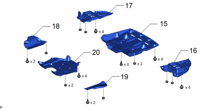 Courtesy of © TOYOTA, LICENSE AGREEMENT TMS1002
| Procedure |
Part Name Code |
Courtesy of © TOYOTA, LICENSE AGREEMENT TMS1002
|
|
|
| 15 |
NO. 1 FLOOR UNDER COVER |
58398F |
- |
- |
- |
| 16 |
TRANSMISSION OIL COOLER UNDER COVER LH |
32912B |
- |
- |
- |
| 17 |
TRANSMISSION OIL COOLER UNDER COVER RH |
32911 |
- |
- |
- |
| 18 |
NO. 1 DIFFERENTIAL SUPPORT PROTECTOR |
52383E |
- |
- |
- |
| 19 |
NO. 2 DIFFERENTIAL SUPPORT PROTECTOR |
52384C |
- |
- |
- |
| 20 |
REAR SUSPENSION BRACE COVER |
53661B |
- |
- |
- |
 Courtesy of © TOYOTA, LICENSE AGREEMENT TMS1002
| Procedure |
Part Name Code |
Courtesy of © TOYOTA, LICENSE AGREEMENT TMS1002
|
|
|
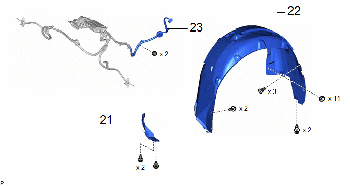
| 21 |
ROCKER PANEL MOULDING PROTECTOR LH |
75866E |
- |
- |
- |
| 22 |
REAR WHEEL HOUSE LINER LH |
65638 |
- |
- |
- |
| 23 |
PARKING BRAKE WITH BRACKET ACTUATOR ASSEMBLY |
46300 |
- |
- |
- |
 Courtesy of © TOYOTA, LICENSE AGREEMENT TMS1002
| Procedure |
Part Name Code |
Courtesy of © TOYOTA, LICENSE AGREEMENT TMS1002
|
|
|
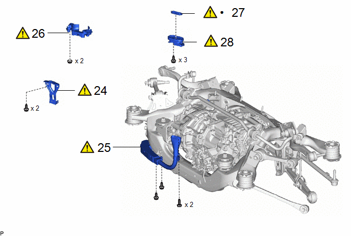
| 24 |
MOTOR CABLE BRACKET |
G1143 |
See step 24 |
- |
- |
| 25 |
MOTOR CABLE |
G1148 |
See step 25 |
- |
- |
| 26 |
CONNECTOR COVER |
82821T |
See step 26 |
- |
- |
| 27 |
MOTOR CABLE TERMINAL CAP |
G114D |
See step 27 |
- |
- |
| 28 |
WIRING HARNESS CONNECTOR |
82H24 |
See step 28 |
- |
- |
 Courtesy of © TOYOTA, LICENSE AGREEMENT TMS1002
| Procedure |
Part Name Code |
Courtesy of © TOYOTA, LICENSE AGREEMENT TMS1002
|
|
|
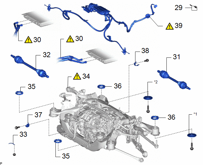
| 29 |
DRAIN HYBRID TRANSAXLE FLUID |
- |
- |
See step 29 |
- |
| 30 |
OIL COOLER TUBE SUB-ASSEMBLY |
32906F |
See step 30 |
- |
- |
| 31 |
REAR DRIVE SHAFT ASSEMBLY LH |
42340B |
- |
- |
- |
| 32 |
REAR DRIVE SHAFT ASSEMBLY RH |
42330 |
- |
- |
- |
| 33 |
NO. 1 BOND CABLE |
82001 |
- |
- |
- |
| 34 |
REAR SUSPENSION MEMBER SUB-ASSEMBLY |
51206A |
See step 34 |
- |
- |
| 35 |
REAR LOWER SUSPENSION MEMBER STOPPER |
52278C |
- |
- |
- |
| 36 |
REAR UPPER SUSPENSION MEMBER STOPPER |
52277B |
- |
- |
- |
| 37 |
MOTOR CABLE BRACKET |
G1143 |
- |
- |
- |
| 38 |
NO. 2 MOTOR CABLE BRACKET |
G1143F |
- |
- |
- |
| 39 |
PARKING BRAKE ACTUATOR ASSEMBLY WITH BRACKET |
46300 |
See step 39 |
- |
- |
| *1 |
REAR LOWER SUSPENSION MEMBER STOPPER LH |
*2 |
REAR LOWER SUSPENSION MEMBER STOPPER RH |
 Courtesy of © TOYOTA, LICENSE AGREEMENT TMS1002
| Procedure |
Part Name Code |
Courtesy of © TOYOTA, LICENSE AGREEMENT TMS1002
|
|
|
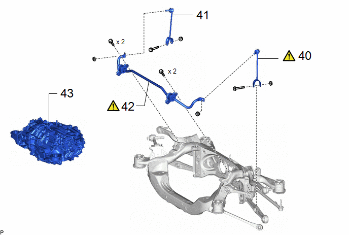
| 40 |
REAR STABILIZER LINK ASSEMBLY LH |
48840A |
See step 40 |
- |
- |
| 41 |
REAR STABILIZER LINK ASSEMBLY RH |
48830D |
- |
- |
- |
| 42 |
REAR STABILIZER BAR |
48812 |
See step 42 |
- |
- |
| 43 |
FCV WITH MOTOR TRANSAXLE ASSEMBLY |
30600R |
- |
- |
- |
 Courtesy of © TOYOTA, LICENSE AGREEMENT TMS1002
| Procedure |
Part Name Code |
Courtesy of © TOYOTA, LICENSE AGREEMENT TMS1002
|
|
|
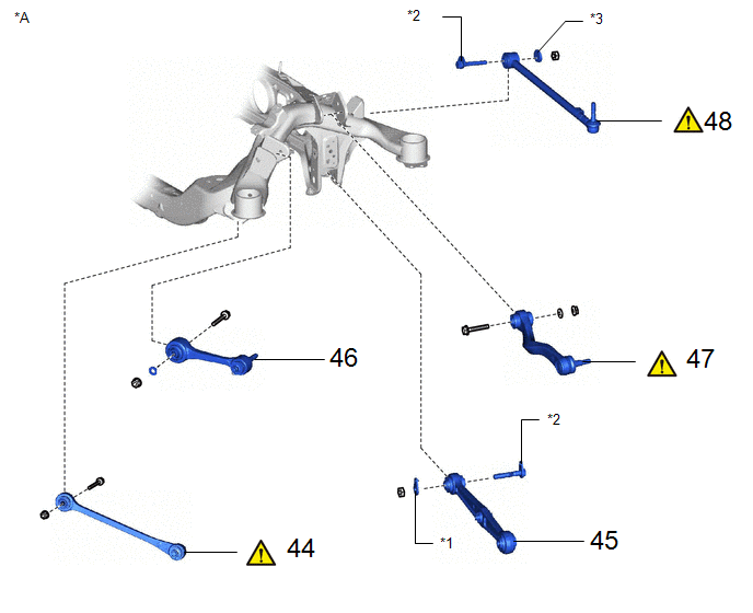
| 44 |
LOWER CONTROL ARM ASSEMBLY LH |
48730 |
See step 44 |
- |
- |
| 45 |
REAR NO. 2 SUSPENSION ARM ASSEMBLY LH |
48740F |
- |
- |
- |
| 46 |
REAR NO. 1 SUSPENSION ARM ASSEMBLY LH |
48720A |
- |
- |
- |
| 47 |
REAR UPPER CONTROL ARM ASSEMBLY LH |
48790 |
See step 47 |
- |
- |
| 48 |
TOE CONTROL LINK SUB-ASSEMBLY LH |
48706B |
See step 48 |
- |
- |
| *A |
for LH Side |
- |
- |
| *1 |
REAR NO. 2 SUSPENSION TOE ADJUST PLATE |
*2 |
REAR SUSPENSION ARM ATTACHMENT SUB-ASSEMBLY |
| *3 |
REAR SUSPENSION TOE ADJUST CAM SUB-ASSEMBLY |
- |
- |
 Courtesy of © TOYOTA, LICENSE AGREEMENT TMS1002
| Procedure |
Part Name Code |
Courtesy of © TOYOTA, LICENSE AGREEMENT TMS1002
|
|
|
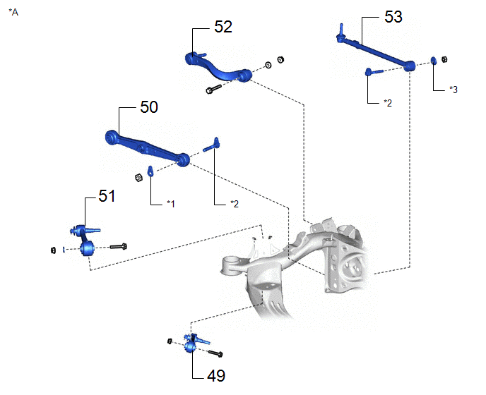
| 49 |
LOWER CONTROL ARM ASSEMBLY RH |
48720 |
- |
- |
- |
| 50 |
REAR NO. 2 SUSPENSION ARM ASSEMBLY RH |
48730F |
- |
- |
- |
| 51 |
REAR NO. 1 SUSPENSION ARM ASSEMBLY RH |
48710A |
- |
- |
- |
| 52 |
REAR UPPER CONTROL ARM ASSEMBLY RH |
48770A |
- |
- |
- |
| 53 |
TOE CONTROL LINK SUB-ASSEMBLY RH |
48705 |
- |
- |
- |
| *A |
for RH Side |
- |
- |
| *1 |
REAR NO. 2 SUSPENSION TOE ADJUST PLATE |
*2 |
REAR SUSPENSION ARM ATTACHMENT SUB-ASSEMBLY |
| *3 |
REAR SUSPENSION ARM ATTACHMENT SUB-ASSEMBLY |
- |
- |
 Courtesy of © TOYOTA, LICENSE AGREEMENT TMS1002
| Procedure |
Part Name Code |
Courtesy of © TOYOTA, LICENSE AGREEMENT TMS1002
|
|
|
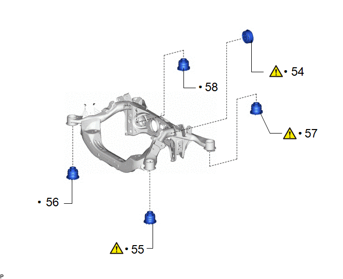
| 54 |
REAR MOTOR MOUNTING INSULATOR |
G2371A |
See step 54 |
- |
- |
| 55 |
REAR SUSPENSION MEMBER FRONT BODY MOUNTING CUSHION LH |
52272A |
See step 55 |
- |
- |
| 56 |
REAR SUSPENSION MEMBER FRONT BODY MOUNTING CUSHION RH |
52271E |
- |
- |
- |
| 57 |
REAR SUSPENSION MEMBER REAR BODY MOUNTING CUSHION (for LH Side) |
52275A |
See step 57 |
- |
- |
| 58 |
REAR SUSPENSION MEMBER REAR BODY MOUNTING CUSHION (for RH Side) |
52275A |
- |
- |
- |
|
N.m (kgf/cm, ft.lbf): Specified torque |
- |
- |
The necessary procedures (adjustment, calibration, initialization, or registration) that must be performed after parts are removed, installed, or replaced during the rear suspension member removal/installation are shown below.
Necessary Procedure After Parts Removed/Installed/Replaced
| Replacement Part or Procedure |
Necessary Procedures |
Effects/Inoperative when not Performed |
Link |
- Rear disc (Including removal and installation)
- Parking brake shoe (Including removal and installation)
- Parking brake actuator assembly with bracket (Removed and installed)
|
Parking brake bedding |
Electric parking brake system |
Refer to UTILITY [11/2020 - ] |
| Suspension, tires, etc.* |
Rear television camera assembly optical axis (Back camera position setting) |
Parking assist monitor system |
Refer to CALIBRATION [11/2020 - 12/2022] |
- Parking assist ECU initialization
- Adjust steering angle
- Rear television camera view adjustment (for Rear camera detection system)
|
Panoramic view monitor system |
Refer to CALIBRATION [11/2020 - 12/2022] |
| Perform headlight ECU sub-assembly LH initialization |
Automatic headlight beam level control system |
Refer to REGISTRATION [11/2021 - 12/2023] |
w/ Headlight ECU:
- Replacement of the rear height control sensor sub-assembly LH, removal and reinstallation of the rear height control sensor sub-assembly LH, replacement of the suspension, etc. Have been performed
|
Perform headlight ECU sub-assembly LH initialization |
Automatic headlight beam level control system |
Refer to REGISTRATION [11/2021 - 12/2023] |
| Disconnect cable from negative auxiliary battery terminal |
Memorize steering angle neutral point |
Parking assist monitor system |
Refer to INITIALIZATION [11/2020 - 12/2022] |
| Panoramic view monitor system |
Refer to INITIALIZATION [11/2020 - 12/2022] |
*: The vehicle height changes because of suspension or tire replacement.
NOTE:
- Immediately after installing the brake pads, the braking performance may be reduced. Always perform a road test in a safe place while paying attention to the surroundings.
- After replacing the front disc brake pads, the brake pedal may feel soft due to clearance between the front disc brake pads and front disc. Depress the brake pedal several times until the brake pedal feels firm.
- When removing or installing the front disc brake cylinder assembly, pushing back the disc brake piston may cause a large clearance between the brake pads and brake disc. When the brake pedal is depressed with a large clearance between the brake pads and the brake disc, DTC C13DB00, C13DC00, C13DD00, C13DE00, C140000 and/or C140A00 related to abnormal brake fluid pressure may be stored. Make sure to clear any DTCs after performing this procedure.
- While the auxiliary battery is connected, even if the ignition switch is off, the brake control system activates when the brake pedal is depressed or any door courtesy switch turns on. Therefore, when servicing the brake system components, do not operate the brake pedal or open/close the doors while the auxiliary battery is connected.
HINT:
When the cable is disconnected/reconnected to the auxiliary battery terminal, systems temporarily stop operating. However, each system has a function that completes learning the first time the system is used.