Test No. 4: Fuel Gauge Does Not Operate Or Abnormal Operation
- Turn ignition off. Locate and disconnect 5-pin electrical harness connector at fuel pump. Turn ignition on. If fuel gauge indicates EMPTY, go to next step. If fuel gauge does not indicate EMPTY, check wiring harness for short. See INSTRUMENT CLUSTER
in SYSTEM WIRING DIAGRAMS article. After repairs have been made, perform confirmation test. See CONFIRMATION TEST .
- Turn ignition off. Using jumper wires, connect a 12-volt, 3.4-watt light bulb across fuel pump 5-pin electrical harness connector terminals No. 2 and 3. See Fig 1. With ignition on, test light should be on and fuel gauge needle should move toward FULL. If test light is off and gauge needle does not move, check wiring harness for open circuit. Repair as necessary. See INSTRUMENT CLUSTER
in SYSTEM WIRING DIAGRAMS article. After repairs have been made, perform confirmation test. See CONFIRMATION TEST . If wire harness is okay, go to next step.
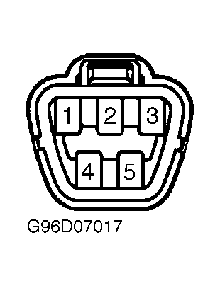 Courtesy of © TOYOTA, LICENSE AGREEMENT TMS1002
- Turn ignition off. Remove instrument cluster. See INSTRUMENT CLUSTER under REMOVAL & INSTALLATION. Disconnect 22-pin electrical harness connector C9 and 18-pin electrical harness connector C10 from back side of instrument cluster. See Figure. Measure resistance across specified terminals of fuel gauge. See Figure. See FUEL GAUGE RESISTANCE table. If resistance is within specification, go to next step. If resistance is not within specification, replace instrument cluster. See INSTRUMENT CLUSTER under REMOVAL & INSTALLATION. After repairs have been made, perform confirmation test. See CONFIRMATION TEST .
FUEL GAUGE RESISTANCE
| Test Between Terminals |
Specification (Ohms) |
| "A" & "B" |
250 |
| "C" & "D" |
250 |
- Test fuel sending unit. See FUEL SENDING UNIT under COMPONENT TESTS. If fuel sending unit is okay, go to next step. If fuel sending unit is not okay, replace fuel sending unit. After repairs have been made, perform confirmation test. See CONFIRMATION TEST .
- Check ECU-ACC (5-amp), ECU-B (7.5-amp), ECU-IG No. 2 (10-amp), GAUGE No. 1 (10-amp), PANEL (5-amp), and RADIO (15-amp) fuses in driver side junction block located under left side of instrument panel. See Figure. If fuses are okay, go to next step. If fuses are defective, repair short in wiring connected to identified fuse. See INSTRUMENT CLUSTER
in SYSTEM WIRING DIAGRAMS article. After repairs have been made, perform confirmation test. See CONFIRMATION TEST .
- Check multi-display information center and instrument cluster ground circuits. See INSTRUMENT CLUSTER
in SYSTEM WIRING DIAGRAMS article. If ground circuits are faulty, repair and retest system. If ground circuits are okay, substitute original multi-display information center or instrument cluster with a known-good unit and recheck system operation. If system operates properly, original multi-display information center or instrument cluster was defective. If system still does not operate properly, perform multi-display information center, instrument cluster and instrument cluster/multi-display information center electrical harness pin voltage checks. See MULTI-DISPLAY INFORMATION CENTER , INSTRUMENT CLUSTER and INSTRUMENT CLUSTER/MULTI-DISPLAY INFORMATION CENTER ELECTRICAL HARNESS
under PIN VOLTAGE TESTS. Check wiring harnesses and electrical connectors for an intermittent problem. Repair wiring harnesses or connectors as necessary. If voltage values, harnesses and connectors are okay, replace multi-display information center and/or instrument cluster. After repairs have been made, perform confirmation test. See CONFIRMATION TEST .