Diagnosis & Repair
WARNING: This page is about a different car, the 2003 Toyota 4Runner. However, it is still accessible from the selected car via links, so may be relevant.
NOTE:
When 2 or more DTCs for misfiring cylinder are recorded repeatedly and DTC P0300 does not exist, it indicates misfires were detected and recorded at different times. If misfire cannot be reproduced, the reason may be because vehicle was driven with a lack of fuel, improper fuel, fouled spark plug, etc. Using Toyota hand-held tester or scan tool, read FREEZE FRAME data. Freeze frame data records engine conditions when malfunction is detected. If COOLANT TEMP displayed in freeze frame data is less than 176°F (80°C), there is a possibility that misfire only exists during warm-up.
NOTE:
If oscilloscope is available, fuel injector operation on misfiring cylinder may be checked by reading the fuel injector signal waveform pattern and fuel injector duration signal waveform pattern which may be checked by connecting oscilloscope between ECM 34-pin connector E4 terminal No. 7 (E01) (White/Black wire) and fuel injector driver terminals (#10 - #60) for misfiring cylinder at ECM with engine idling. ECM is located behind glove box. See Figure. For ECM electrical connector terminal identification, see Figure. For fuel injector driver identification, see IDENTIFYING ECM FUEL INJECTOR DRIVER TERMINALS . Fuel injector signal waveform pattern and fuel injector duration signal waveform pattern should be properly displayed within proper intervals. See Fig 10.
For circuit wiring diagram, diagnosis and repair procedure, see Fig 1-Fig 9
.
When it is necessary to perform TEST DRIVE CONFIRMATION pattern, see TEST DRIVE CONFIRMATION .
When ignition coil(s) and/or ignition coil(s) and ignitor circuit diagnosis is necessary, go to DTC P0351-DTC P0356: IGNITION COIL "A"-"F" PRIMARY/SECONDARY CIRCUIT . If necessary to check or replace engine timing chain and/or timing gear(s), see appropriate article in ENGINES. For vacuum or EVAP hose routing, see VACUUM DIAGRAMS
article. For testing of systems or components, see BASIC DIAGNOSTIC PROCEDURES - V6 & V8
article or SYSTEM & COMPONENT TESTING - V6 & V8
article. For adjustments, see ON-VEHICLE ADJUSTMENTS - V6 & V8
article. For removal and installation of components, see REMOVAL & INSTALLATION - V6 & V8
article.
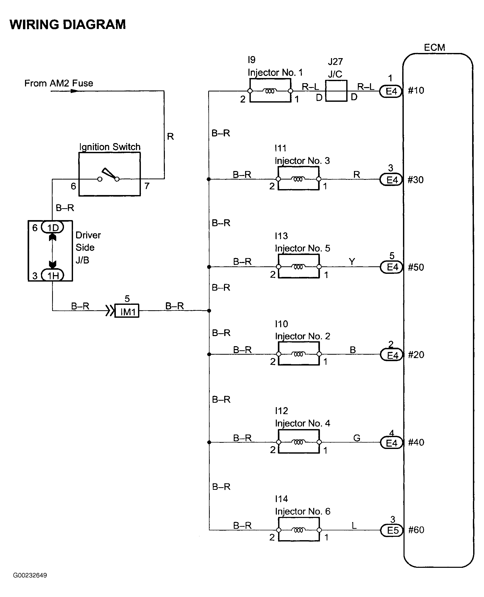 Courtesy of © TOYOTA, LICENSE AGREEMENT TMS1002
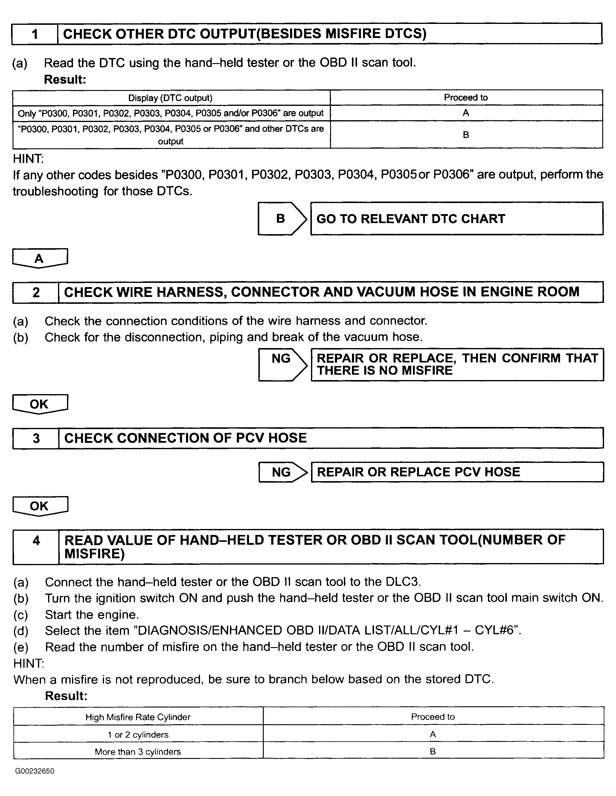 Courtesy of © TOYOTA, LICENSE AGREEMENT TMS1002
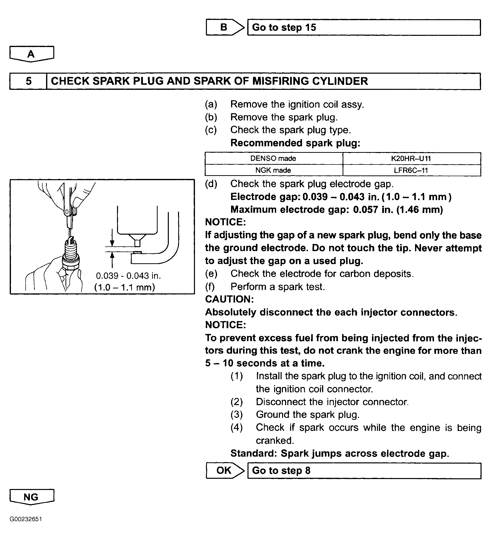 Courtesy of © TOYOTA, LICENSE AGREEMENT TMS1002
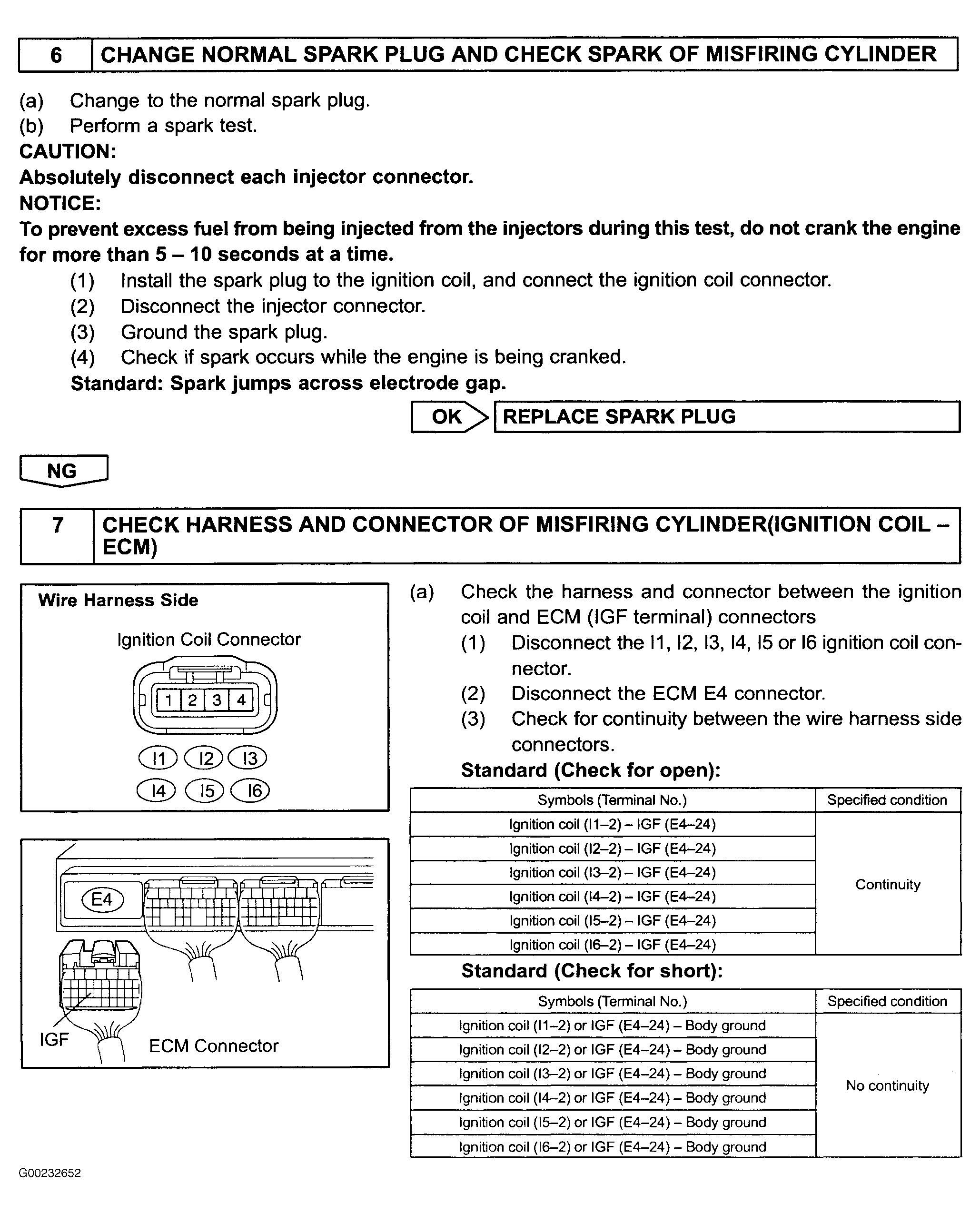 Courtesy of © TOYOTA, LICENSE AGREEMENT TMS1002
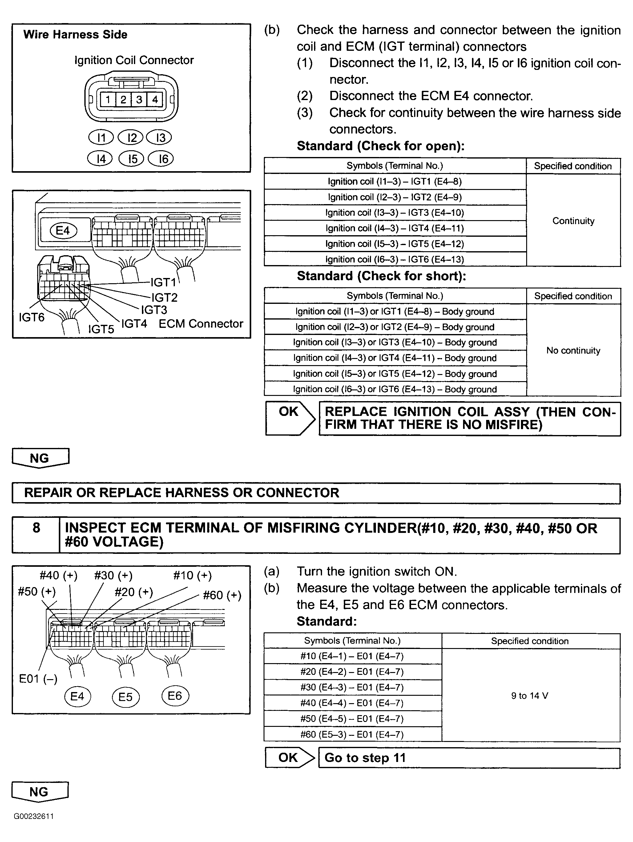 Courtesy of © TOYOTA, LICENSE AGREEMENT TMS1002
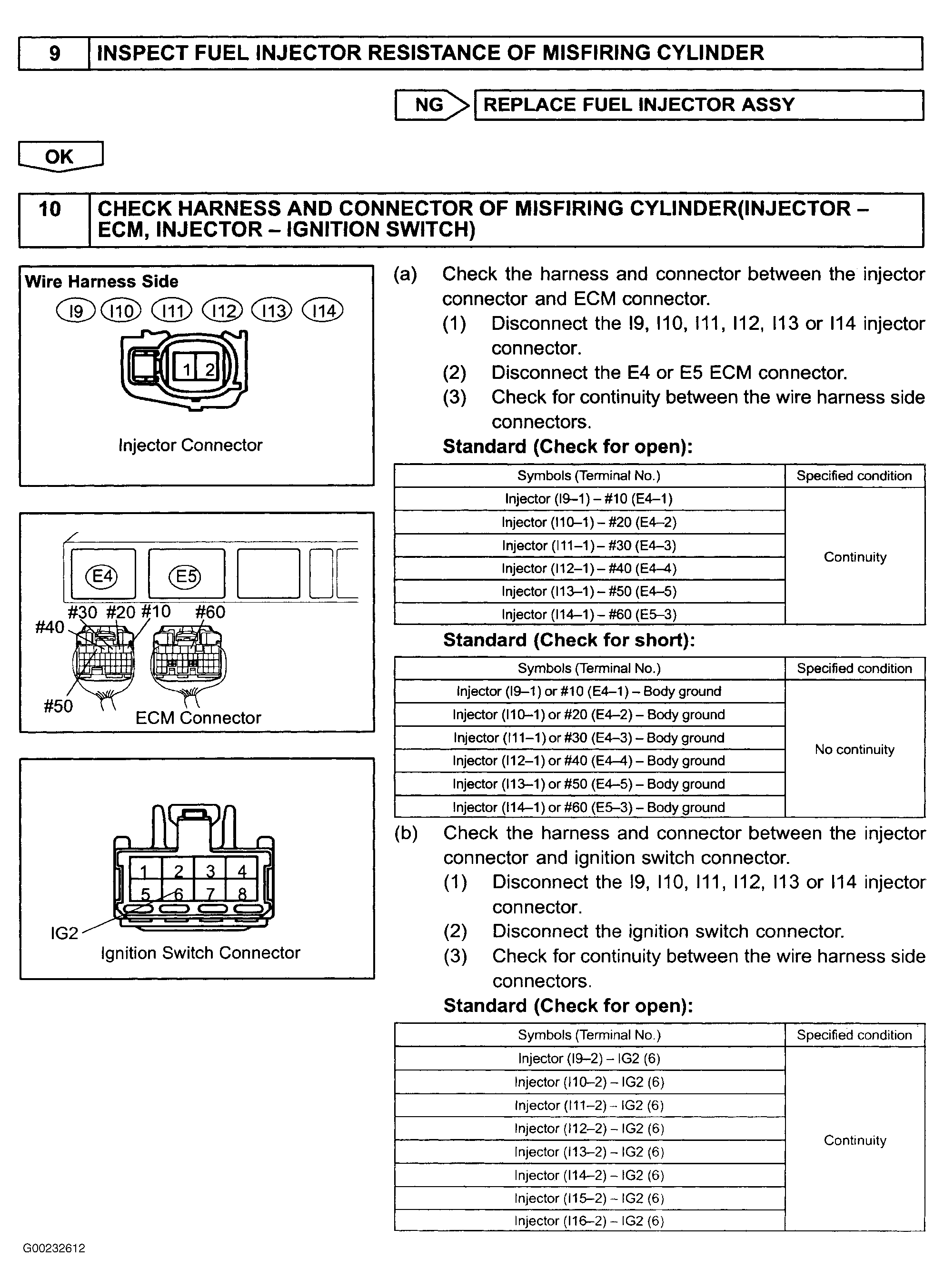 Courtesy of © TOYOTA, LICENSE AGREEMENT TMS1002
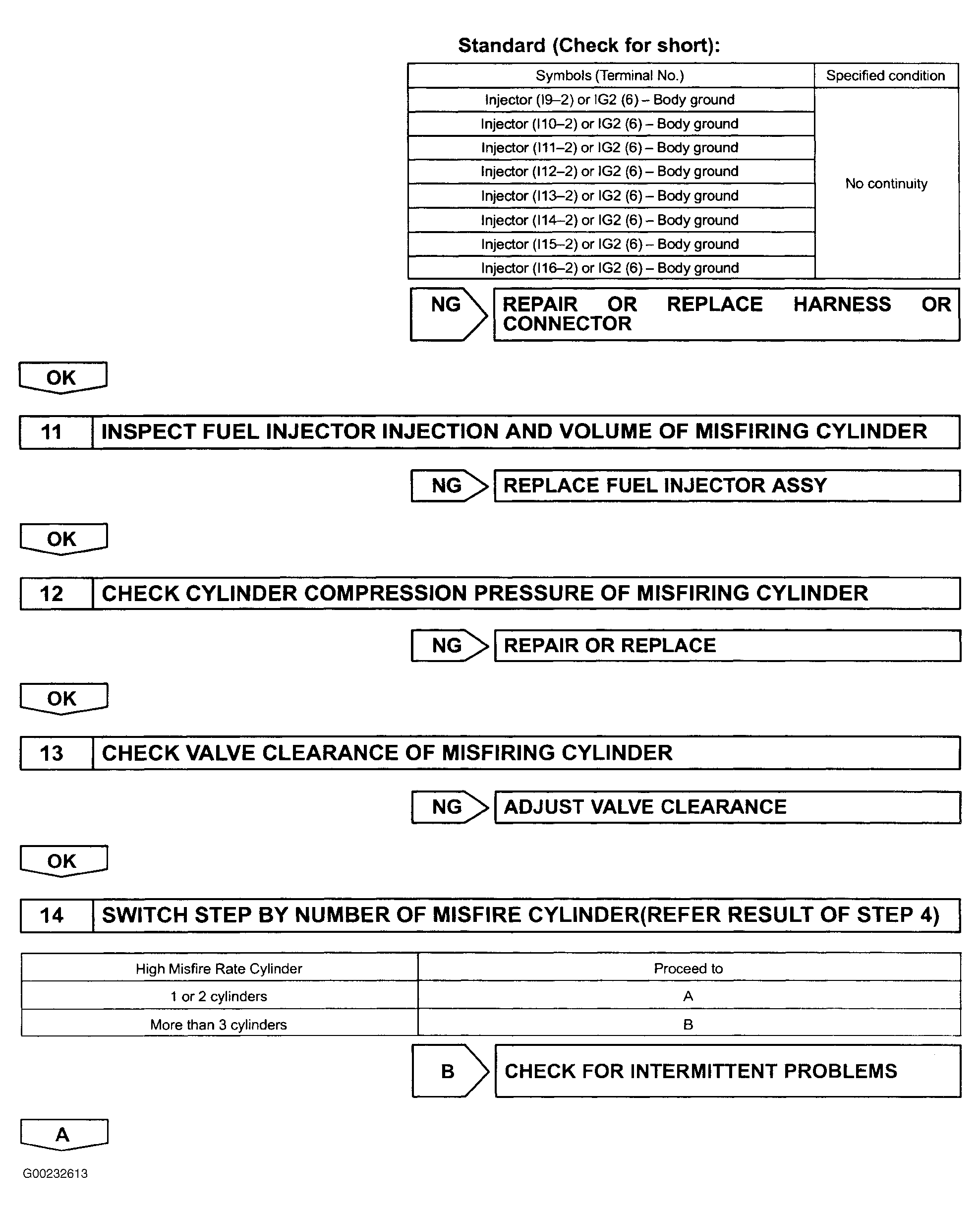 Courtesy of © TOYOTA, LICENSE AGREEMENT TMS1002
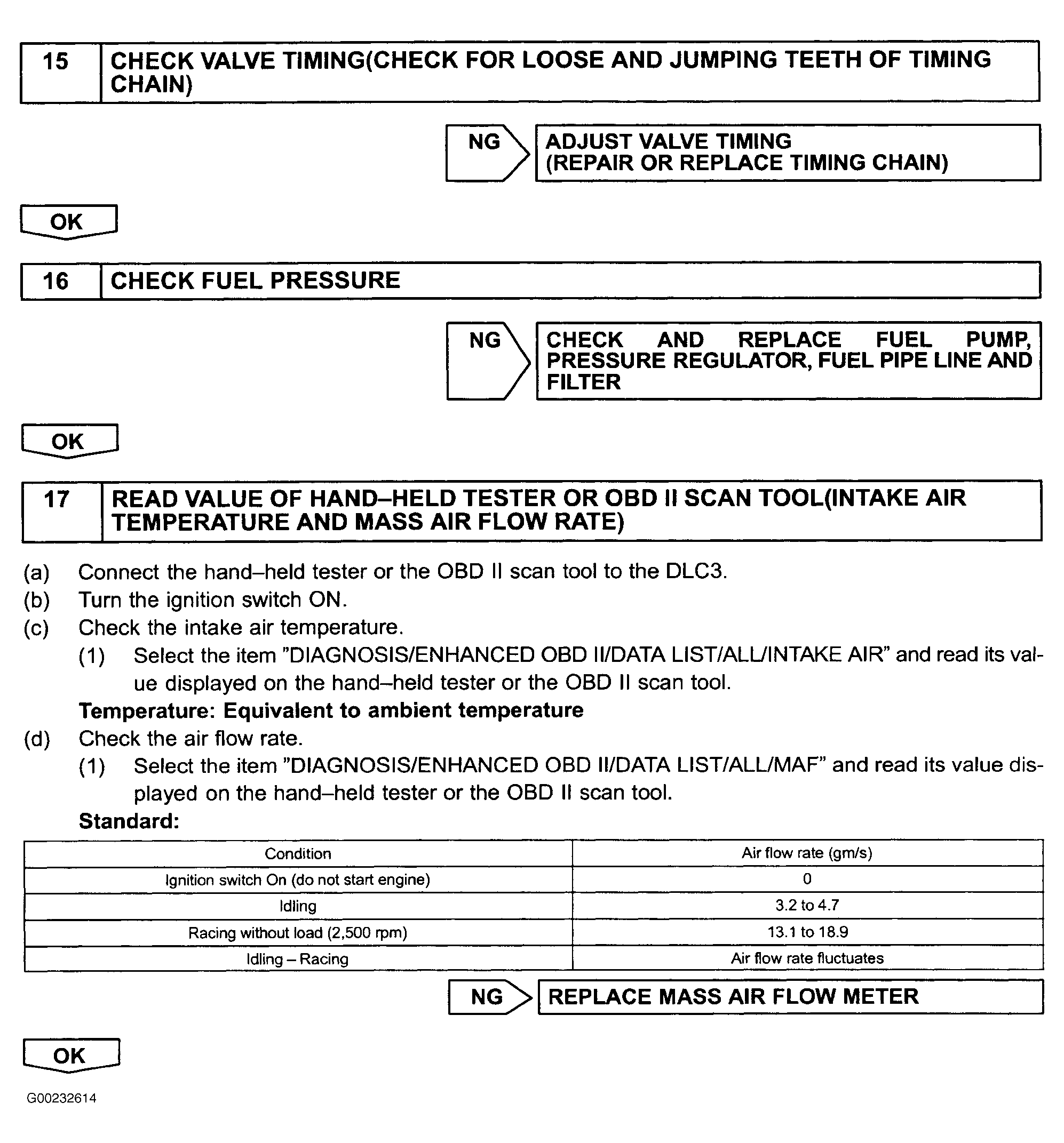 Courtesy of © TOYOTA, LICENSE AGREEMENT TMS1002
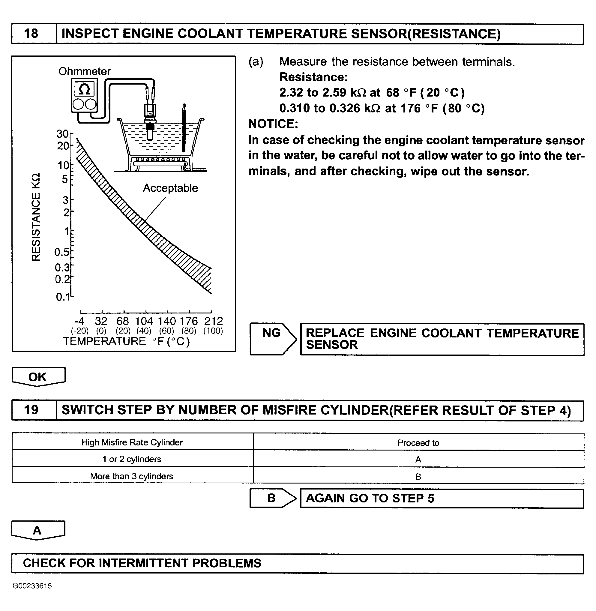 Courtesy of © TOYOTA, LICENSE AGREEMENT TMS1002
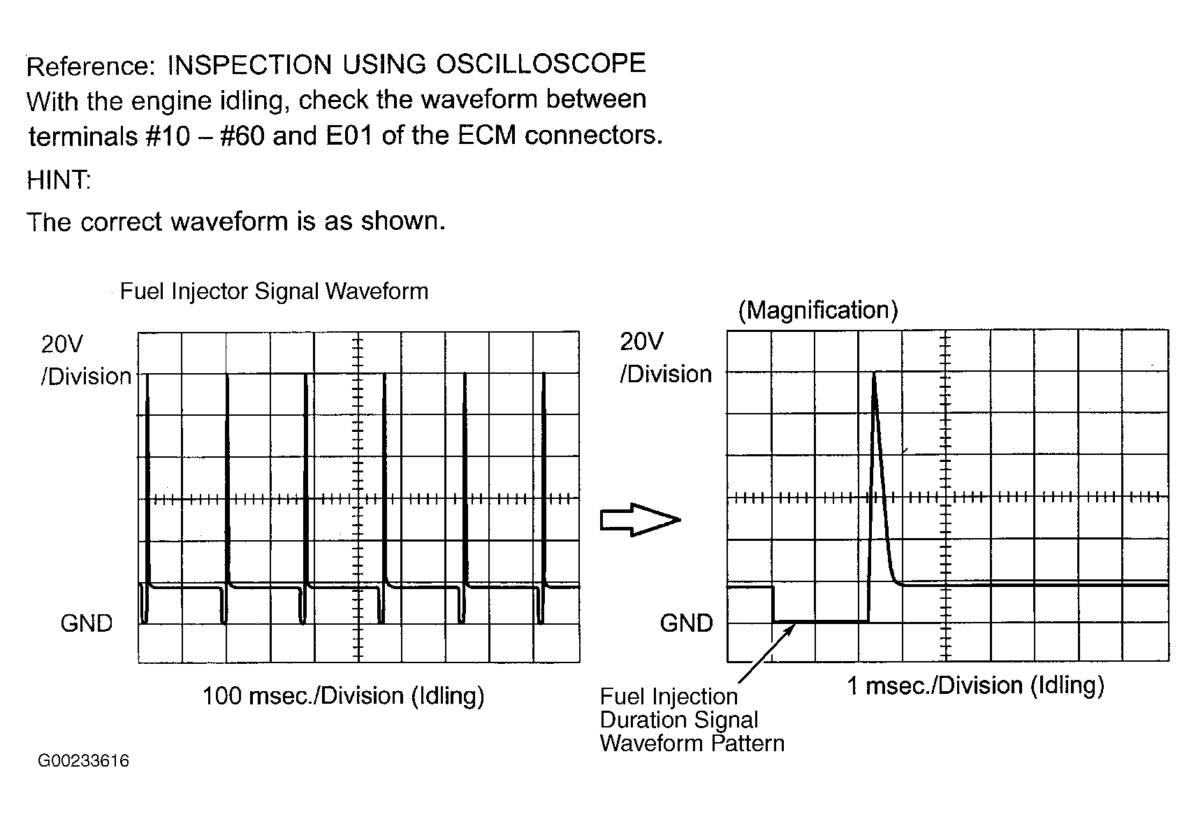 Courtesy of © TOYOTA, LICENSE AGREEMENT TMS1002
 IDENTIFYING ECM FUEL INJECTOR DRIVER TERMINALS
| Fuel Injector No. |
ECM Electrical Connector & Terminal |
Wire Color |
| 1 |
E4 Terminal No. 1 (#10) |
Red/Black |
| 2 |
E4 Terminal No. 2 (#20) |
Black |
| 3 |
E4 Terminal No. 3 (#30) |
Red |
| 4 |
E4 Terminal No. 4 (#40) |
Green |
| 5 |
E4 Terminal No. 5 (#50) |
Yellow |
| 6 |
E5 Terminal No. 3 (#60) |
Blue |