Hazard Warning Switch
- Ensure HAZARD and TURN fuses are good. Ensure flasher is good. For turn signal flasher testing, see
STEERING COLUMN SWITCHES article. For turn signal flasher location, see TURN SIGNAL FLASHER LOCATION table. With hazard warning switch removed from instrument panel, ensure battery voltage exists at switch wiring harness connector terminals No. 1 (ECHO), No. 8 and 10 (Camry, Camry Solara and MR2), or terminals No. 6 and 7 (Avalon, Celica and Corolla). See Fig 1-Fig 3
. If battery voltage does not exist, check/repair fuses and wiring harness circuits. See WIRING DIAGRAMS . If battery voltage exists, go to next step.
- Using DVOM, ensure switch continuity exists between indicated terminals with switch in specified position. See HAZARD WARNING SWITCH CONTINUITY table. If continuity is not as specified, replace switch. If continuity is as specified, check wiring circuits. See WIRING DIAGRAMS .
TURN SIGNAL FLASHER LOCATION
| Model |
Location |
| Avalon |
Above Left Kick Panel |
| Camry, Camry Solara, Celica, Corolla & Prius |
Behind Left Kick Panel |
| ECHO |
In Instrument Panel Fuse/Relay Block |
| MR2 |
Behind Left Side Of Instrument Cluster |
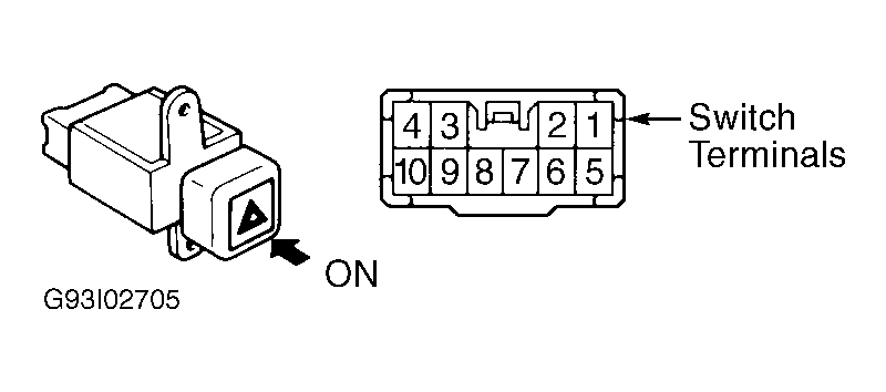 Courtesy of © TOYOTA, LICENSE AGREEMENT TMS1002
 Courtesy of © TOYOTA, LICENSE AGREEMENT TMS1002
 Courtesy of © TOYOTA, LICENSE AGREEMENT TMS1002
 HAZARD WARNING SWITCH CONTINUITY
| Switch Position |
Terminals No. |
Continuity |
| Avalon |
| Off |
5 & 7 |
Yes |
| On |
1, 2, 3 & 4, 5 & 6 |
Yes |
| Camry |
| Off |
7 & 10 |
Yes |
| On |
5, 6 & 9; 7 & 8 |
Yes |
| Camry Solara |
| Off |
7 & 10 |
Yes |
| On |
4, 5, 6 & 9; 7 & 8 |
Yes |
| Celica |
| Off |
5 & 7 |
Yes |
| On |
1, 2 & 4, 5 & 6 |
Yes |
| Corolla |
| Off |
5 & 7 |
Yes |
| On |
1, 2, 3 & 4; 5 & 6 |
Yes |
| ECHO |
| Off |
N/A |
No |
| On |
1 & 2 |
Yes |
| MR2 |
| Off |
7 & 10 |
Yes |
| On |
4, 5, 6 & 9; 7 & 8 |
Yes |
| Prius |
| Off |
3 & 4 |
No |
| On |
3 & 4 |
Yes |