Disassembly (With Electronic Locking Differential)
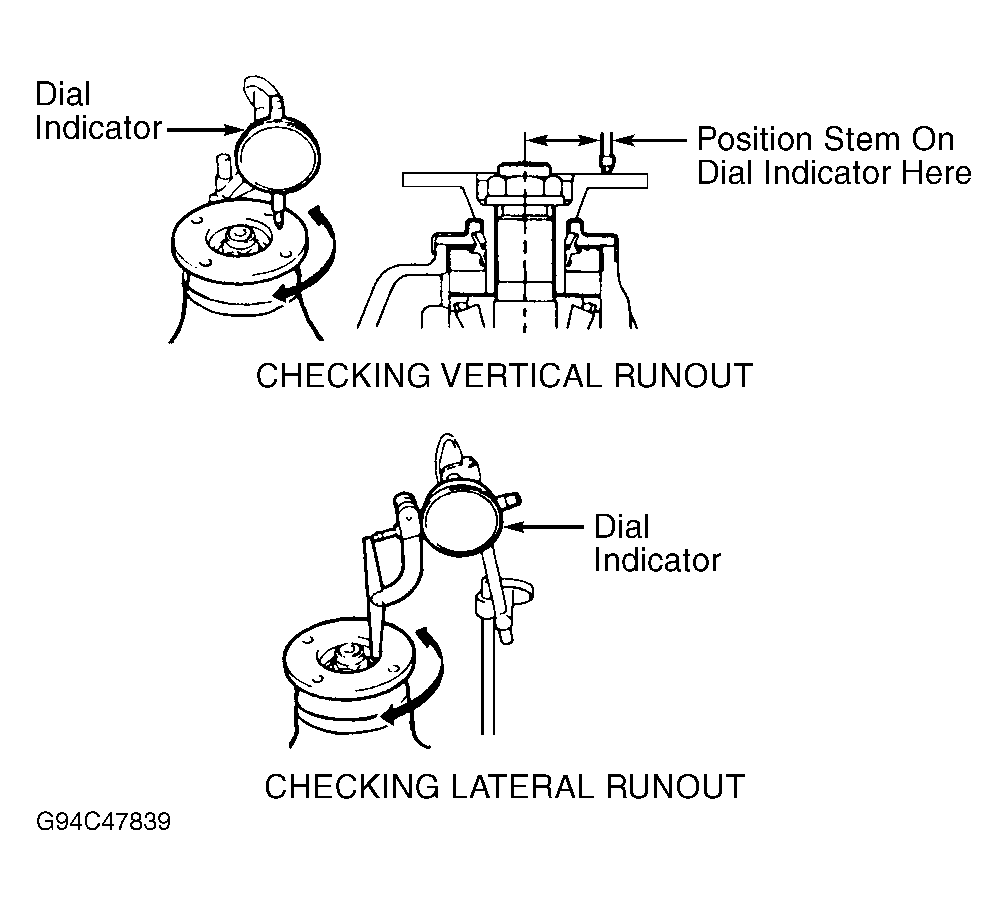
- Using dial indicator, check vertical and lateral runout on companion flange while rotating companion flange. See Fig 1. Replace companion flange if vertical or lateral runout exceeds specification. See AXLE ASSEMBLY SPECIFICATIONS .
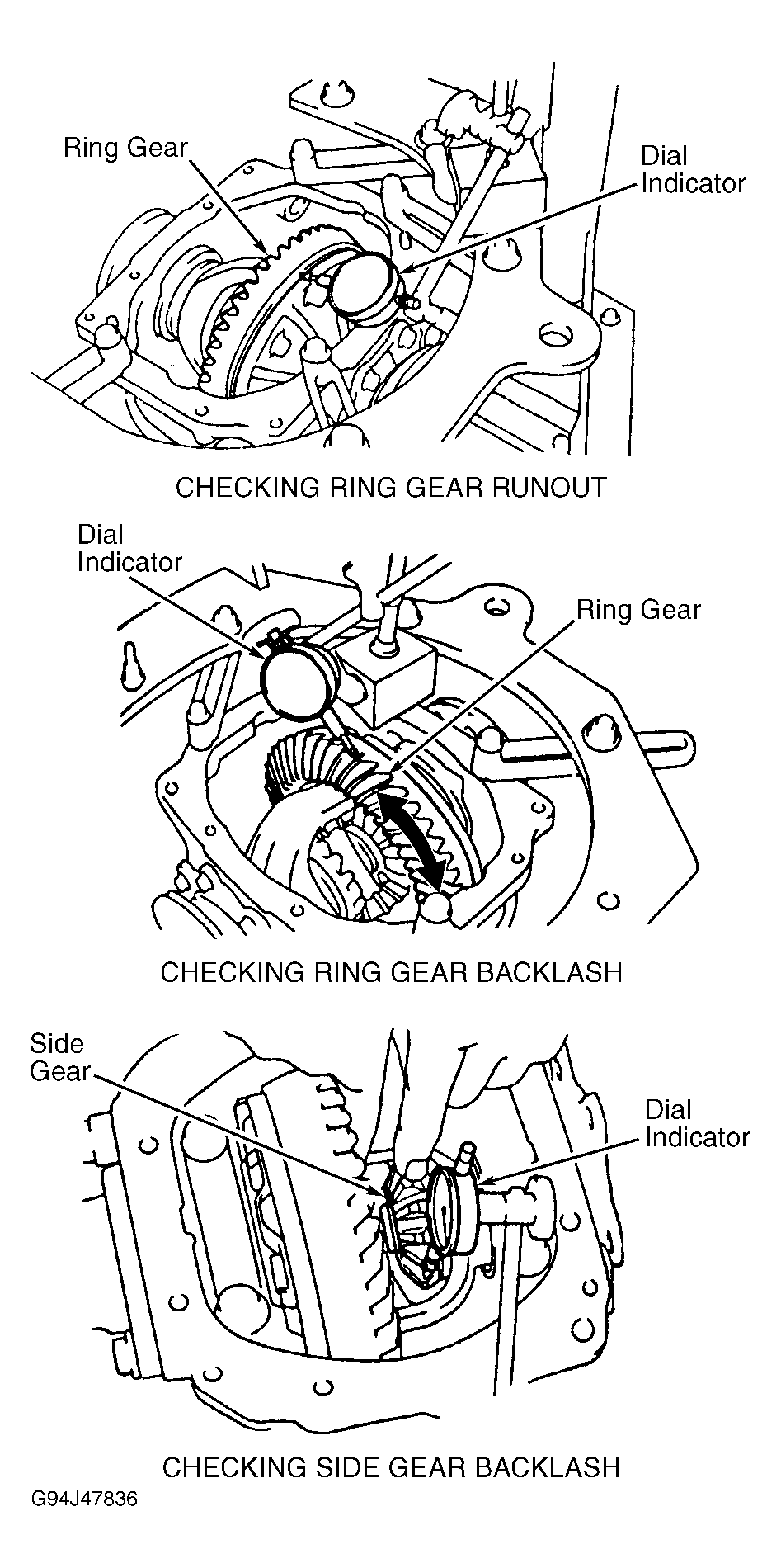
- Using dial indicator, check ring gear runout at backside of ring gear while rotating ring gear. See Fig 2. Replace ring gear and drive pinion as a set if ring gear runout exceeds specification. See AXLE ASSEMBLY SPECIFICATIONS .
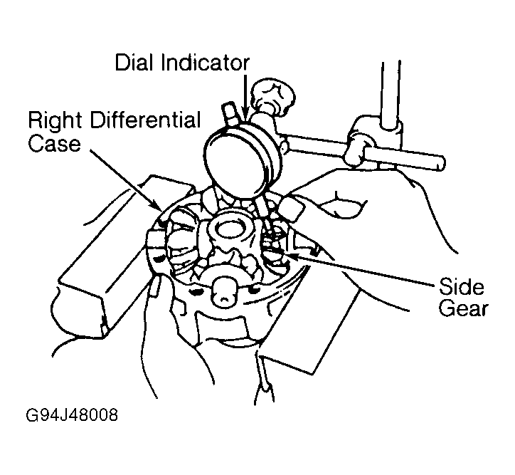
- Using dial indicator, check ring gear backlash while rotating ring gear back and forth, and holding drive pinion from rotating. See Fig 2 or Fig 3
. Ring gear backlash should be within specification. See AXLE ASSEMBLY SPECIFICATIONS . If ring gear backlash is not within specification, adjust side bearing preload or repair as necessary.
- Using INCH-lb. torque wrench installed on drive pinion nut, measure drive pinion rotating torque required to start rotation of drive pinion to determine drive pinion bearing preload for reassembly reference. Drive pinion rotating torque should be within specification. See AXLE ASSEMBLY SPECIFICATIONS .
- Using INCH-lb. torque wrench installed on drive pinion nut, measure total assembled preload required to rotate drive pinion and ring gear for reassembly reference. Total assembled preload should be within specification. See AXLE ASSEMBLY SPECIFICATIONS .
- Check gear tooth contact pattern. See GEAR TOOTH CONTACT PATTERNS article in
GENERAL INFORMATION.
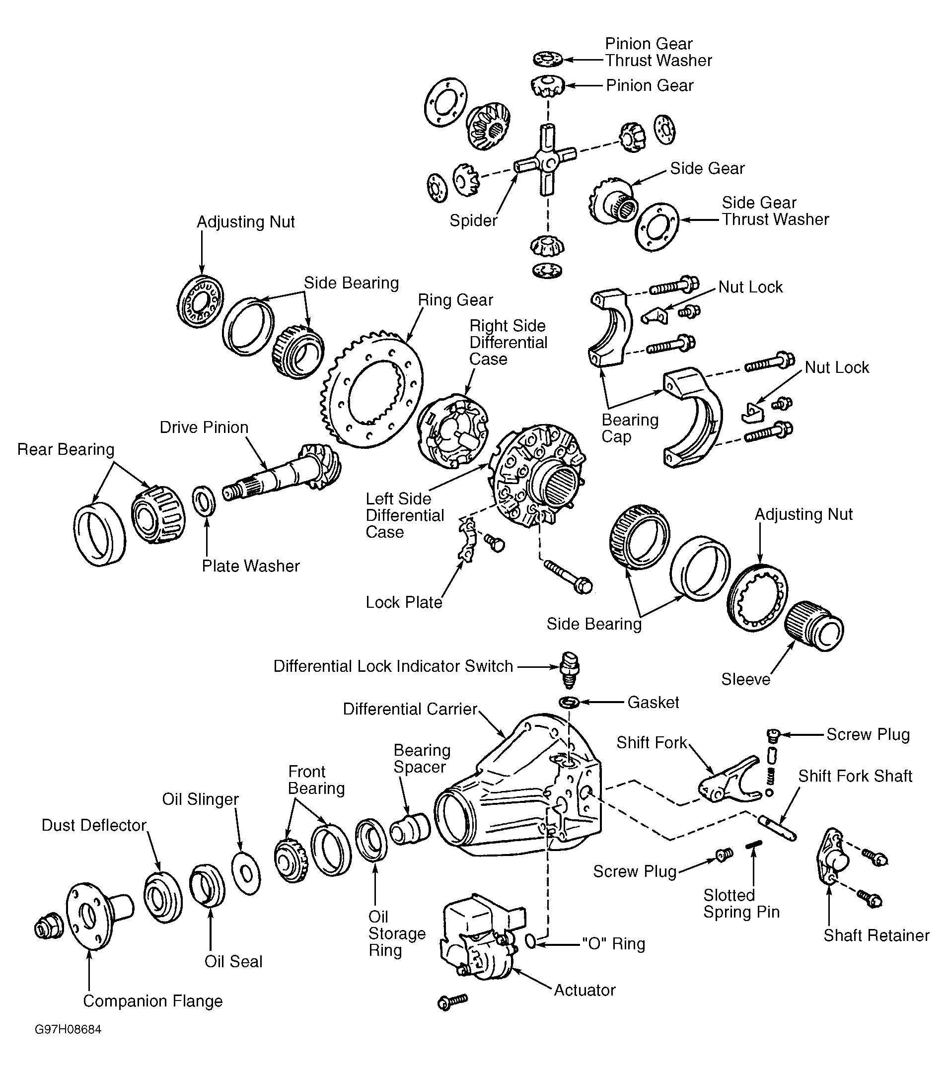
- Remove bolt and electronic locking differential actuator from differential carrier. Remove "O" ring. Remove electronic locking differential indicator switch and gasket. Remove electronic locking differential screw plugs, spring seat, compression spring and ball. See Fig 4.
- Using punch and hammer, remove slotted spring pin. Remove bolts from shaft retainer. Using a plastic hammer, remove shaft retainer. Using a screwdriver, remove shift fork shaft.
- Using hammer and chisel, loosen staked area on drive pinion nut. Remove drive pinion nut.
- Using puller, remove companion flange from drive pinion and oil seal from differential carrier.
- Note direction of oil slinger installation. Remove oil slinger. Using puller, remove front bearing from drive pinion.
- Place reference marks on side bearing caps and differential carrier for reassembly reference. Remove adjusting nut locks located on each side bearing cap. Remove side bearing caps. Remove differential case with side bearing outer races, adjusting nuts and sleeve. Remove shift fork.
- Mark adjusting nut and side bearing race location for reassembly reference. Components must be installed in original location.
- Remove drive pinion from differential carrier. Remove bearing spacer. Press rear bearing from drive pinion (if necessary). Remove washer from drive pinion. If drive pinion or ring gear are damaged, replace them as a set. Using puller, remove front bearing race from differential carrier (if necessary).
- Using hammer and brass drift, tap oil storage ring from differential carrier (if necessary). Using hammer and brass drift, tap rear bearing race from differential carrier (if necessary).
- Place reference mark on ring gear and differential case for reassembly reference. Bend over tabs on lock plates on ring gear bolts. Remove ring gear bolts. Using soft-face hammer, tap ring gear from differential case.
- Reinstall differential case with side bearings and races in differential case. Install side bearing caps and adjusting nuts. Tighten adjusting nuts until no play exists in side bearing. Tighten side bearing cap bolts to specification. See TORQUE SPECIFICATIONS .
- Using dial indicator, check differential case runout at ring gear mounting surface on differential case while rotating differential case. Replace differential case if runout exceeds specification. See AXLE ASSEMBLY SPECIFICATIONS . Remove differential case and components from differential carrier.
- Using puller, remove side bearings from differential case (if necessary). Place reference marks on differential cases for reassembly reference. See Fig 4. Remove differential case bolts uniformly, in small increments.
- Using soft-face hammer, separate differential cases. Remove pinion gears, side gears, thrust washers and spider.
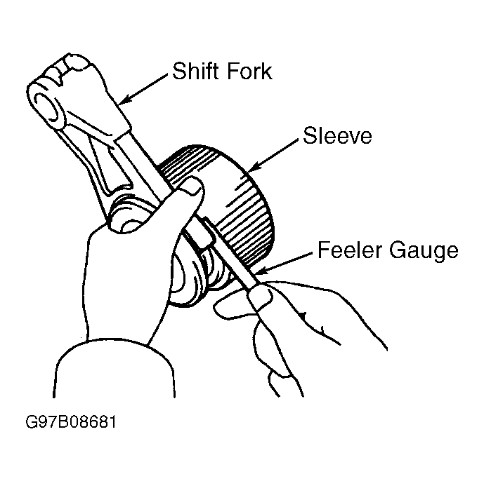
- Install sleeve in left differential case and check that sleeve moves smoothly. Using feeler gauge, measure clearance between shift fork and sleeve. See Fig 5. Clearance should be .006-.014" (0.15-0.36 mm). Using press, remove dust deflector from companion flange (if necessary).
 Courtesy of © TOYOTA, LICENSE AGREEMENT TMS1002
 Courtesy of © TOYOTA, LICENSE AGREEMENT TMS1002
 Courtesy of © TOYOTA, LICENSE AGREEMENT TMS1002
 Courtesy of © TOYOTA, LICENSE AGREEMENT TMS1002
 Courtesy of © TOYOTA, LICENSE AGREEMENT TMS1002