DTC 21: Vehicle Speed Sensor Circuit
- Perform VEHICLE SPEED SENSOR test in CRUISE CONTROL FUNCTION TEST under TROUBLE SHOOTING. If speed sensor input signals are not as specified, go to next step. If speed sensor input signals are as specified, replace cruise control ECU and retest system.
- Check speedometer circuit. See
INSTRUMENT PANELS article. If speedometer circuit is okay, go to next step. If speedometer circuit is not okay, repair wiring harness, connector or instrument cluster as necessary. Retest system.
- Check wiring harness and connectors between cruise control ECU, vehicle speed sensor and instrument cluster. Repair as necessary and retest system. If wiring harness and connectors are okay, go to next step.
- Remove vehicle speed sensor. See Figure. Using jumper wires, connect positive battery terminal to speed sensor terminal No. 1 (Red/Blue wire) and negative battery terminal to terminal No. 2 (Pink wire). Connect voltmeter positive lead to terminal No. 3 (Light Green wire) and negative lead to terminal No. 2 (Pink wire). See Fig 1. Rotate vehicle speed sensor shaft and ensure voltage changes from 0-11 volts or more 4 times per shaft revolution. Replace speed sensor as necessary. If vehicle speed sensor is okay, replace cruise control ECU and retest system.
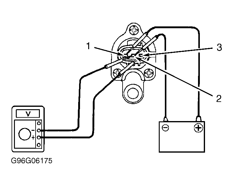 Courtesy of © TOYOTA, LICENSE AGREEMENT TMS1002