Avalon Calif. Emission Vehicles & Camry Calif. Emission Vehicles With A/T
- Two heated A/F sensors are used, one on each exhaust manifold. Heated A/F sensor on rear (firewall side) exhaust manifold may be referred to as bank No. 1 sensor No. 1. Heated A/F sensor on front (radiator side) exhaust manifold may be referred to as bank No. 2 sensor No. 1.
- To check the heater resistance on A/F sensor, disconnect electrical connector at A/F sensor. Using ohmmeter, check resistance between +B and HT terminals on electrical connector. See Fig 1. Replace the A/F sensor if resistance is not.8-1.4 ohms at 68°F (20°C).
- If problem exists in A/F sensor, heater or wiring circuit, a Diagnostic Trouble Code (DTC) may be stored in the Engine Control Module (ECM). For diagnosis of DTC, see appropriate TESTS W/CODES
article.
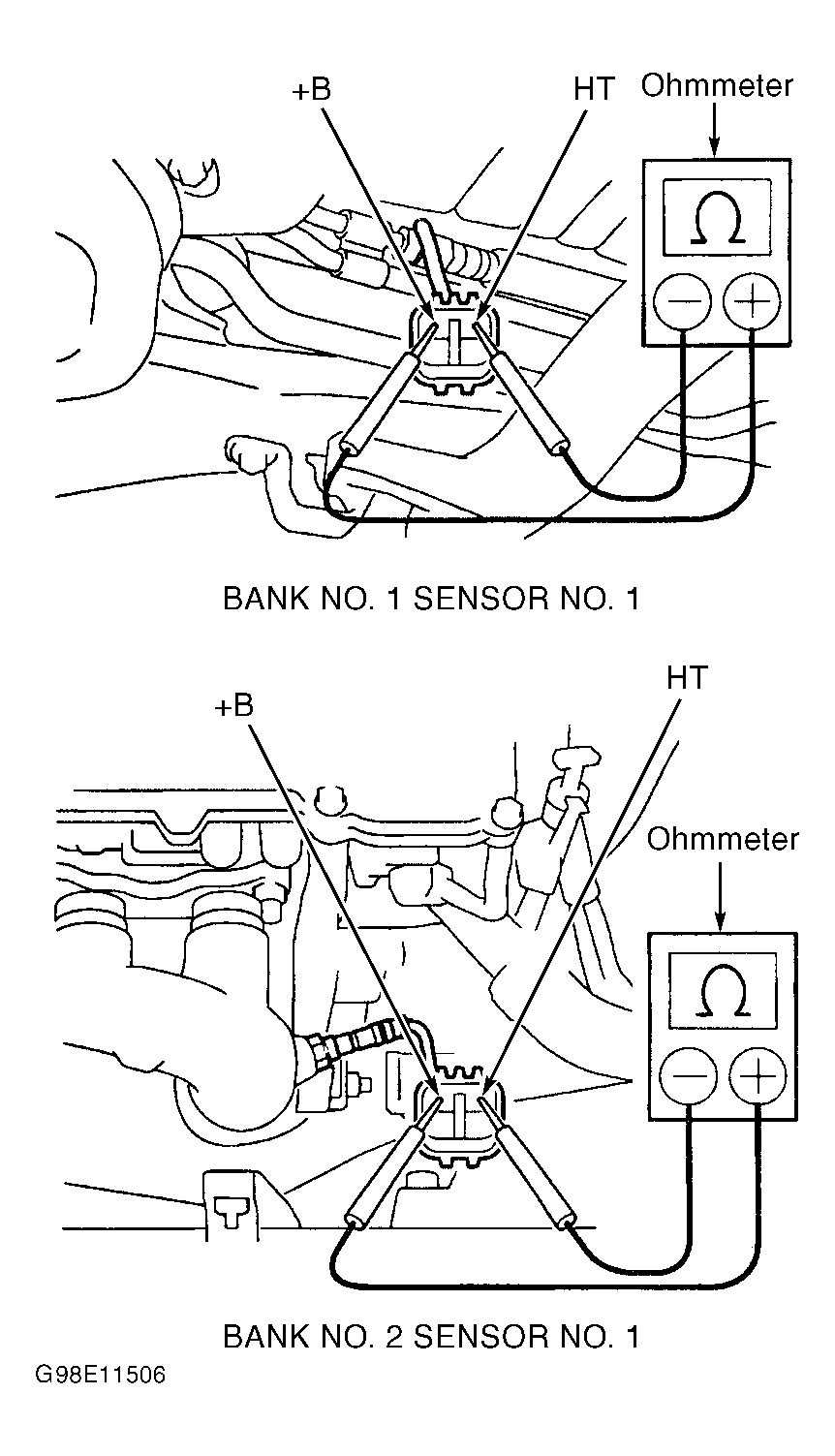 Courtesy of © TOYOTA, LICENSE AGREEMENT TMS1002