Fuel Gauge & Warning Light
- Unplug connector at fuel tank sending unit. Connect a 12-volt, 3.4-watt test light between lead wire and ground. Turn ignition on. Test light should flash and gauge needle should vibrate.
- Turn ignition off. Connect ohmmeter to sending unit terminals. Move sender arm and ensure resistance varies within specifications. See FUEL SENDING UNIT RESISTANCE table. Gauge pointer should move when sender is connected and float arm is moved.
FUEL SENDING UNIT RESISTANCE
| Float Position |
Ohms |
| Full |
1-5 |
| Half |
28-37 |
| Empty |
102-118 |
- To check low fuel warning light sensor, remove fuel sender from tank. Connect battery voltage to sensor terminal. Connect a 12-volt 3.4-watt test light between body of sending unit and ground. With sensor dry, light should come on within 40 seconds. With sensor in gasoline or water, light should not come on.
- Check gauge resistance by measuring across terminals with ohmmeter. See Fig 3. Ignition must be off and connector unplugged. See FUEL & TEMPERATURE GAUGE RESISTANCE table.
FUEL & TEMPERATURE GAUGE RESISTANCE
| Terminal Conn. |
Fuel (Ohms) |
Temp. (Ohms) |
| 1-2 |
55 |
N/A |
| IG-FU |
83 |
N/A |
| FU-E |
156 |
N/A |
| IG-E |
239 |
57 |
| 1-2 |
N/A |
217 |
| IG-TU |
N/A |
135 |
| TU-E |
N/A |
138 |
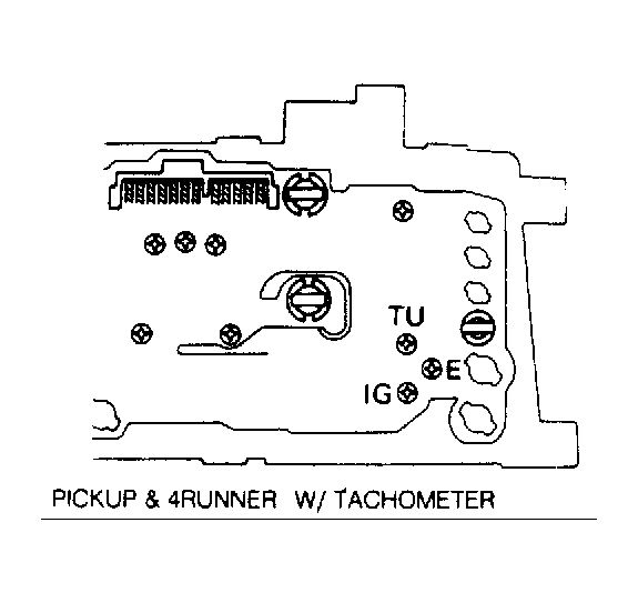 Courtesy of © TOYOTA, LICENSE AGREEMENT TMS1002
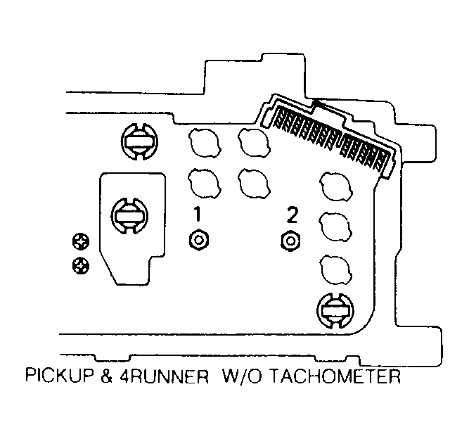 Courtesy of © TOYOTA, LICENSE AGREEMENT TMS1002
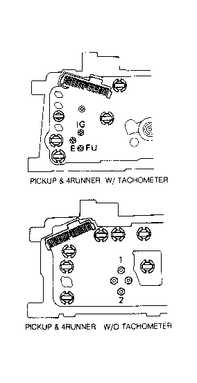 Courtesy of © TOYOTA, LICENSE AGREEMENT TMS1002