- Prepare new drive inverter.
NOTE:
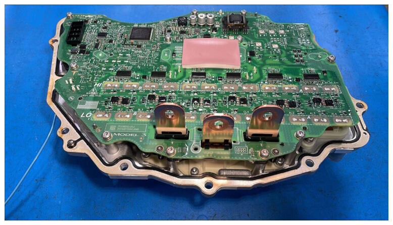
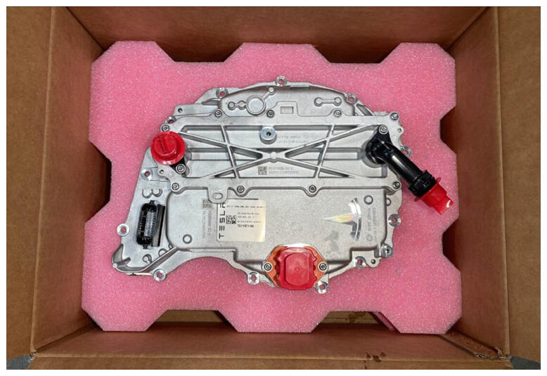
Prepare new drive inverter, Save packaging to MRB old drive inverter, Remove any red protective covers, Refer to https://toolbox.teslamotors.com/articles/6865600 for instruction of installing 2PO inverter to the 3DU vehicle.
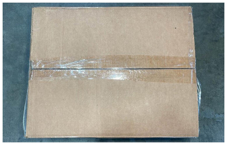 Courtesy of TESLA, INC. Courtesy of TESLA, INC.
|
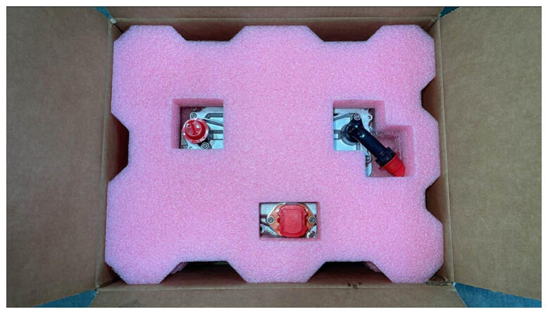 Courtesy of TESLA, INC. Courtesy of TESLA, INC.
|
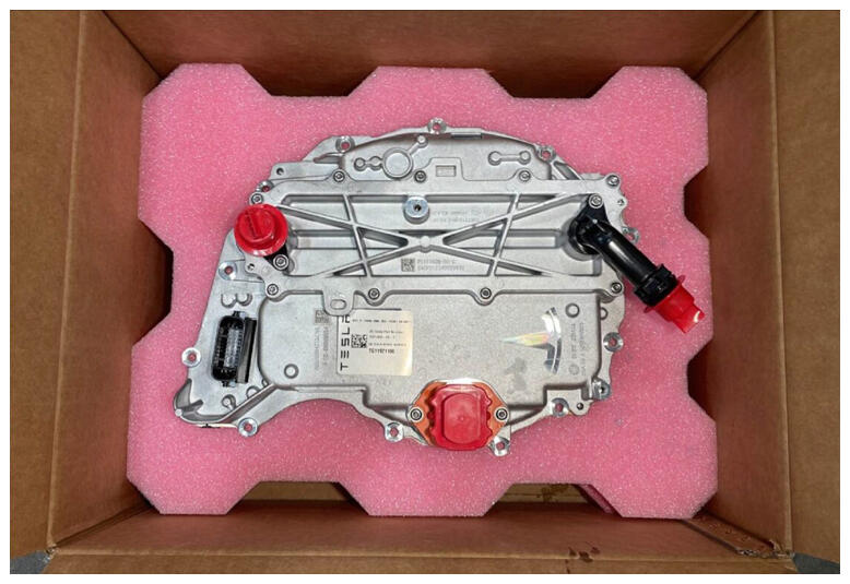 Courtesy of TESLA, INC. Courtesy of TESLA, INC.
|
- Secure ESD strap to new inverter housing.
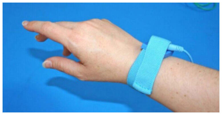 Courtesy of TESLA, INC. Courtesy of TESLA, INC.
|
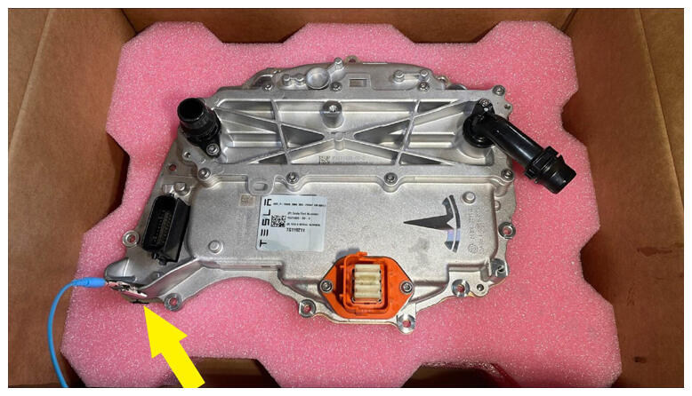 Courtesy of TESLA, INC. Courtesy of TESLA, INC.
|
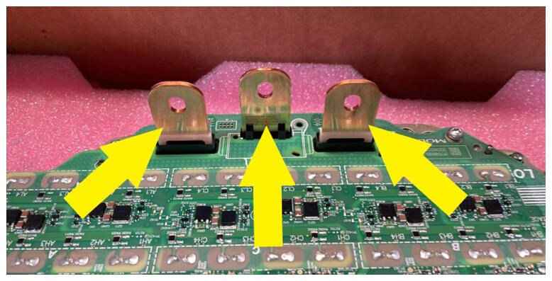
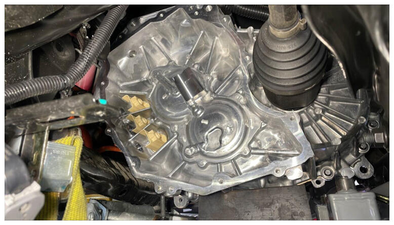
- Clean mating surfaces of the phase lugs.
NOTE:
Clean with IPA, Allow 1 min to dry, Do not leave any debris on the mating surfaces.
 Courtesy of TESLA, INC. Courtesy of TESLA, INC.
|
 Courtesy of TESLA, INC. Courtesy of TESLA, INC.
|
 Courtesy of TESLA, INC. Courtesy of TESLA, INC.
|
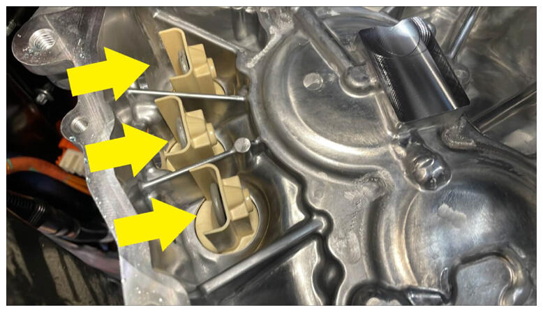 Courtesy of TESLA, INC. Courtesy of TESLA, INC.
|
 Courtesy of TESLA, INC. Courtesy of TESLA, INC.
|
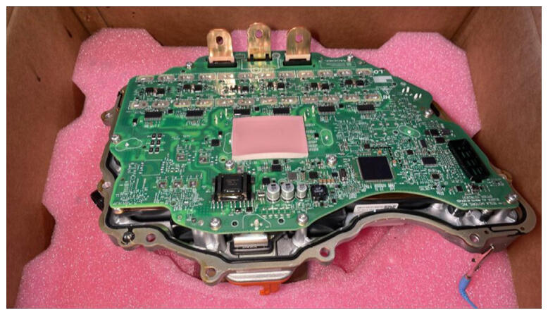
- Inspect the gap pad of the new inverter.
NOTE:
Verify the gap pad is fully attached and covering the discharge resistor array, No resistors should be visible, Gap pad should be clean of debris and evenly adhered. Replace gap pad if it does not match the criteria.
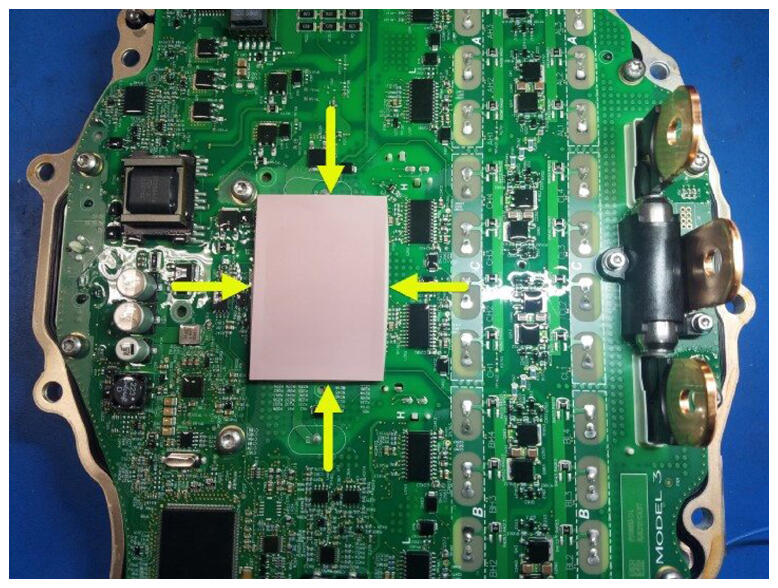 Courtesy of TESLA, INC. Courtesy of TESLA, INC.
|
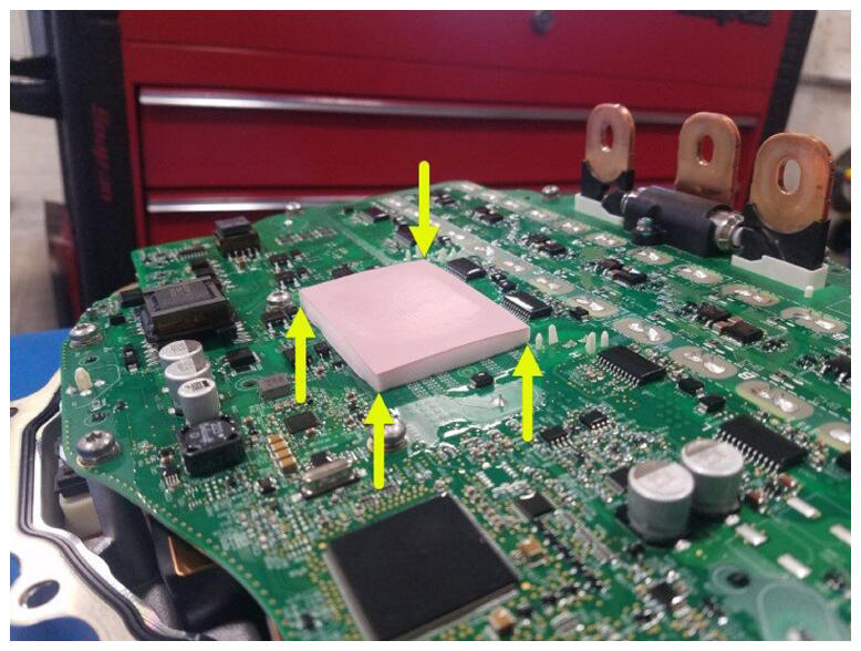 Courtesy of TESLA, INC. Courtesy of TESLA, INC.
|
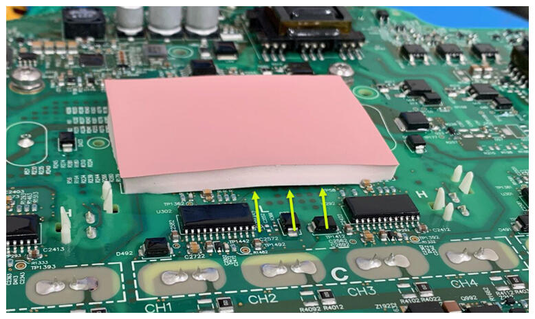 Courtesy of TESLA, INC. Courtesy of TESLA, INC.
|
- Position the inverter with gasket to rear drive unit.
NOTE:
1x gasket, 2x guide pins, Maneuver rear inverter into position, Take caution when maneuvering between subframe do not damage the circuit board, Make sure the 3 phase cables and guides align during installation.
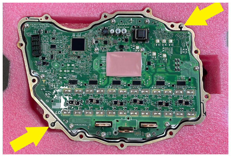 Courtesy of TESLA, INC. Courtesy of TESLA, INC.
|
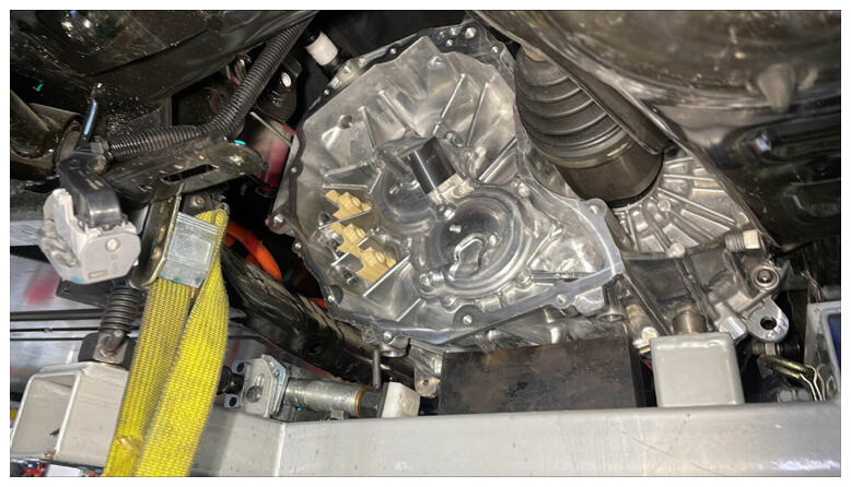 Courtesy of TESLA, INC. Courtesy of TESLA, INC.
|
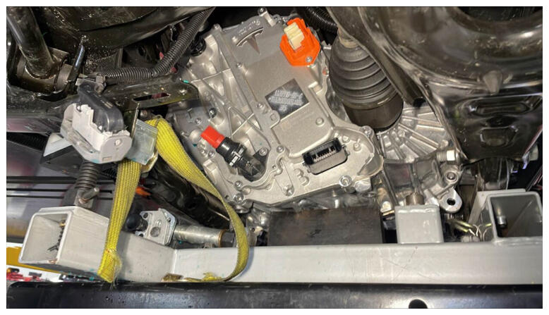 Courtesy of TESLA, INC. Courtesy of TESLA, INC.
|
- Thread in and flush fasteners securing rear inverter to the rear gearbox assembly.
NOTE:
12x bolts, EP10, 12.5 N.m, Fasteners can be re-used, Thread in fasteners until flush, Follow the run down sequence, Do not over torque the fasteners.
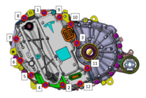 Courtesy of TESLA, INC.
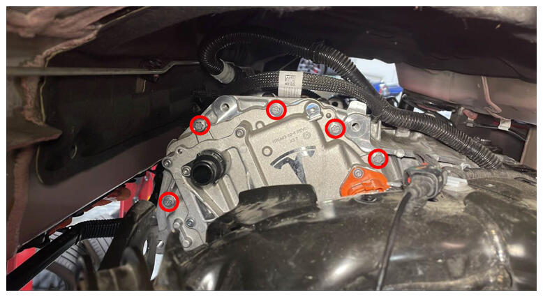 Courtesy of TESLA, INC. Courtesy of TESLA, INC.
|
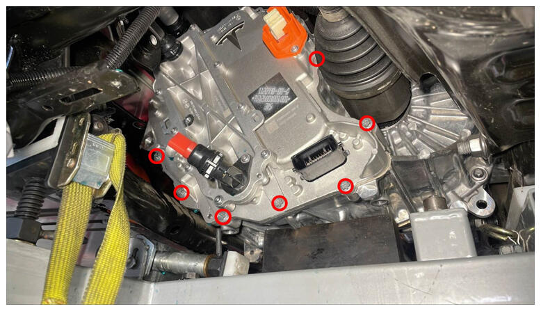 Courtesy of TESLA, INC. Courtesy of TESLA, INC.
|
- Torque bolts securing rear inverter to gearbox assembly.
NOTE:
12x bolts, EP10, 12.5 N.m, Follow the torque sequence.
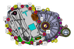 Courtesy of TESLA, INC.
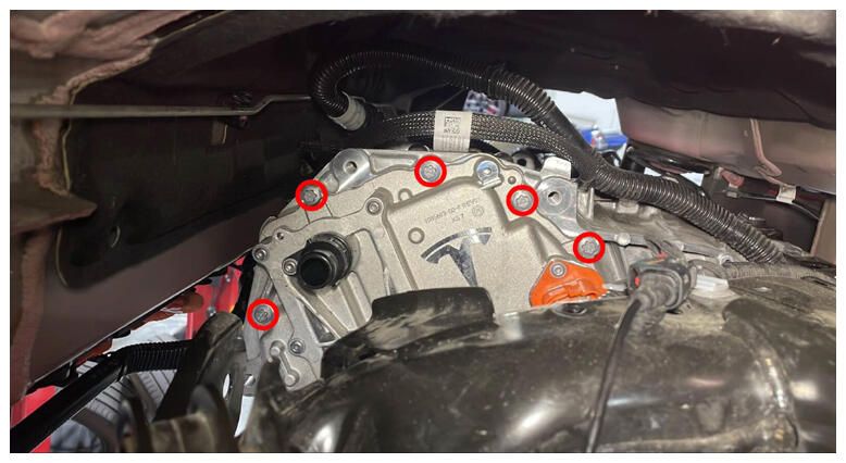 Courtesy of TESLA, INC. Courtesy of TESLA, INC.
|
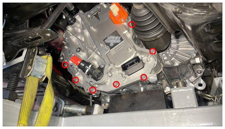 Courtesy of TESLA, INC. Courtesy of TESLA, INC.
|
- Install fasteners securing inverter to the 3 phase lugs.
NOTE:
3x bolts, 10 mm, 11.5 N.m, Fasteners can be re-used, Do not drop fasteners, Use a magnet as needed, If re-using fastener torque to 11.5 N.m. If installing new fasteners torque to 12.5 N.m, Reverse 180 degrees, then torque to 5 N.m + 40 degrees.
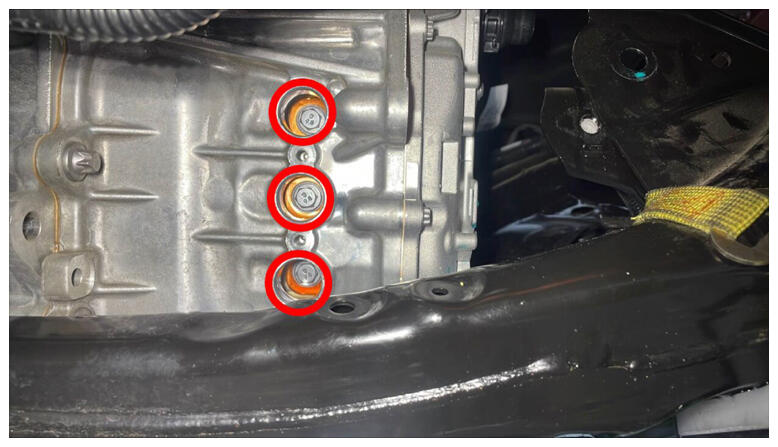 Courtesy of TESLA, INC. Courtesy of TESLA, INC.
|
- Install phase out cover onto RDU.
NOTE:
If phase out cover or O-rings are damaged then replace with a new unit, Lightly lubricate cover as needed, Fully seat cover.
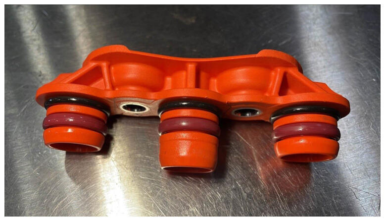 Courtesy of TESLA, INC. Courtesy of TESLA, INC.
|
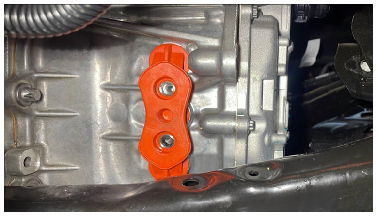 Courtesy of TESLA, INC. Courtesy of TESLA, INC.
|
- Install bolts securing the RDU phase out cover.
NOTE:
2x bolts, EP10, 14 N.m.
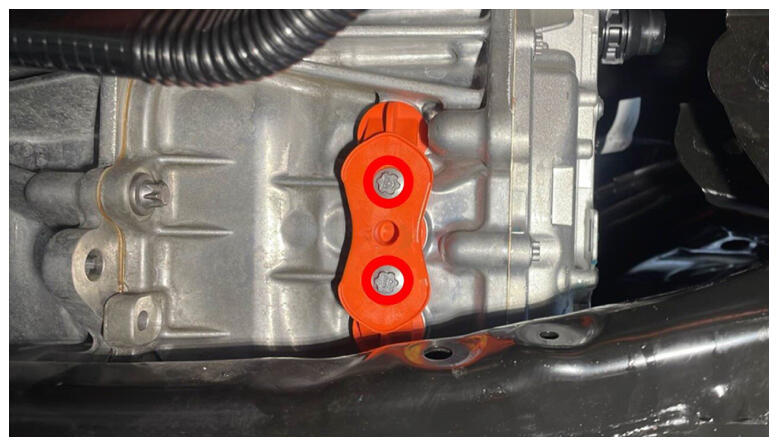 Courtesy of TESLA, INC. Courtesy of TESLA, INC.
|
- Remove ESD wrist strap from inverter.
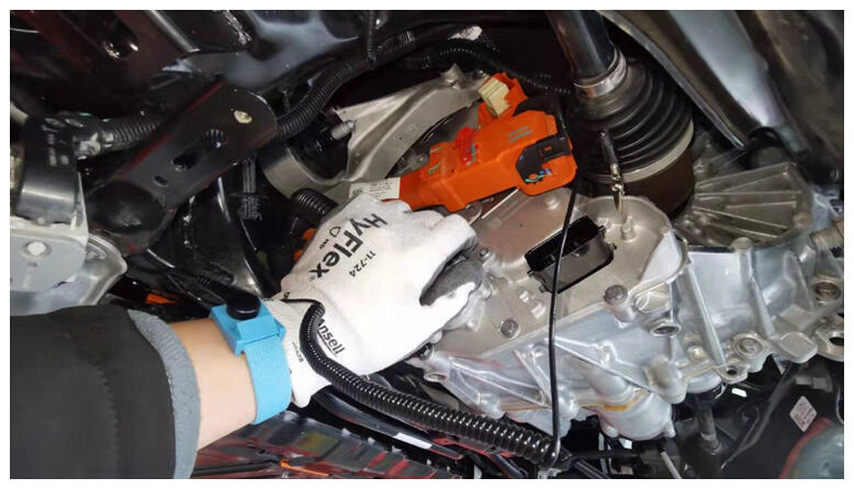 Courtesy of TESLA, INC. Courtesy of TESLA, INC.
|
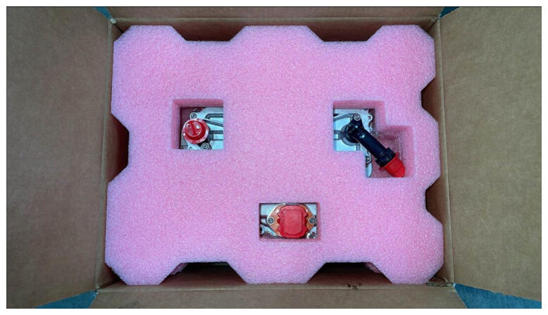
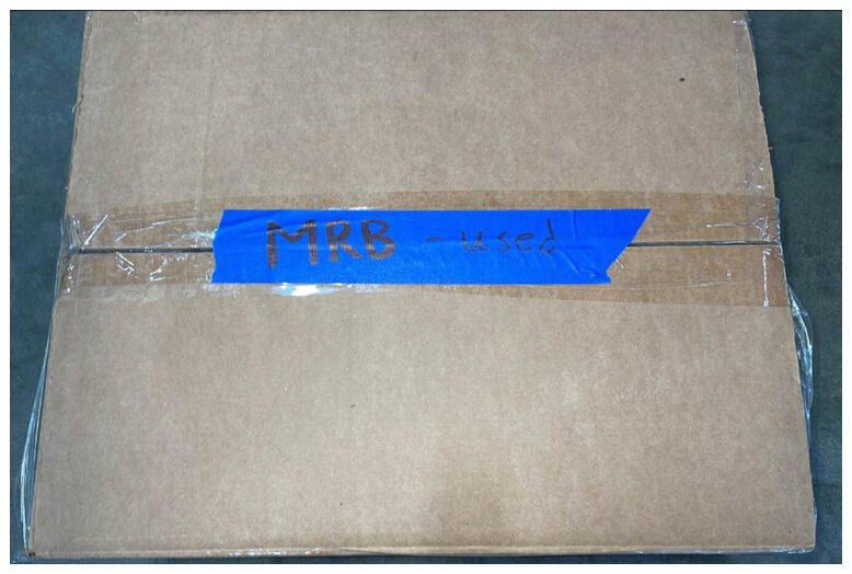
- Take old inverter and prepare for MRB, Label properly for return or disposal.
NOTE:
Use ESD wrist strap, Label inverter for MRB and return to packaging, Secure any protective red caps, Return or dispose of packaging through proper channels, Label the part as MRB.
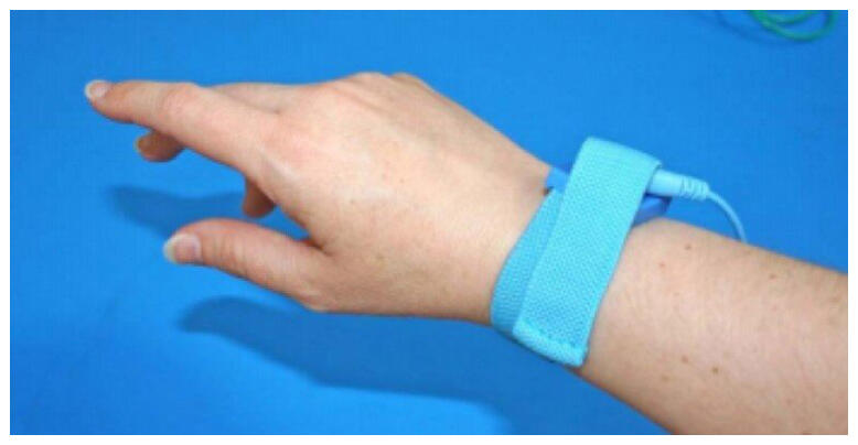 Courtesy of TESLA, INC. Courtesy of TESLA, INC.
|
 Courtesy of TESLA, INC. Courtesy of TESLA, INC.
|
 Courtesy of TESLA, INC. Courtesy of TESLA, INC.
|
 Courtesy of TESLA, INC. Courtesy of TESLA, INC.
|
 Courtesy of TESLA, INC. Courtesy of TESLA, INC.
|
- Install adapter into RDU logic connector.
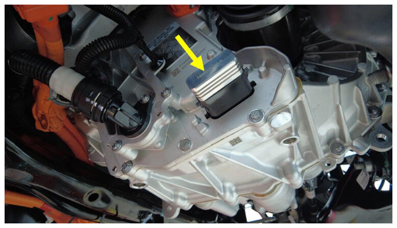 Courtesy of TESLA, INC. Courtesy of TESLA, INC.
|
- Install adapter into rear drive inverter.
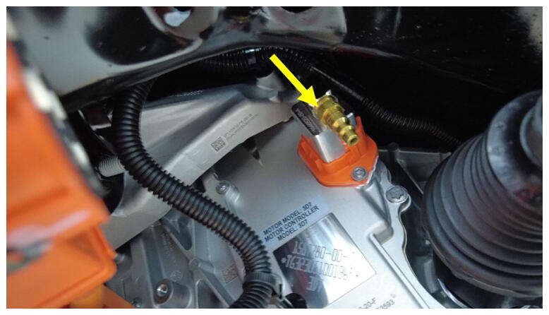 Courtesy of TESLA, INC. Courtesy of TESLA, INC.
|
- Install the leak test adapter into the rear drive inverter.
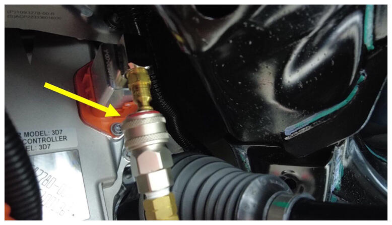 Courtesy of TESLA, INC. Courtesy of TESLA, INC.
|
- Close both valves on the regulator test tool.
NOTE:
By turning valve knobs to a vertical position, The valves are fully closed.
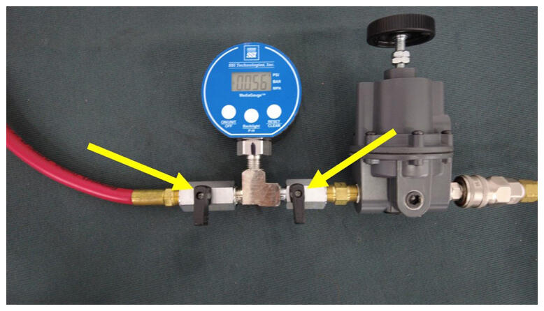 Courtesy of TESLA, INC. Courtesy of TESLA, INC.
|
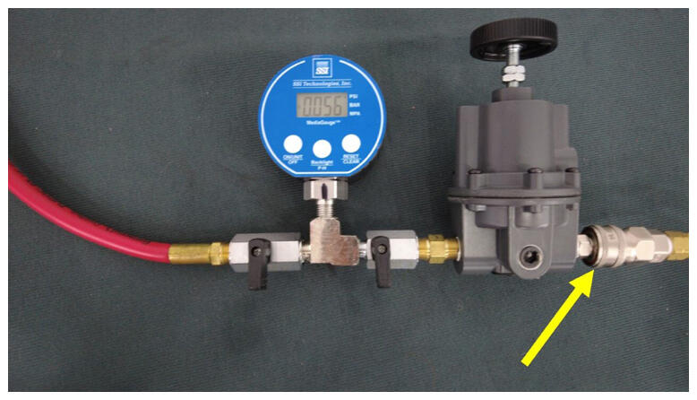
- Connect regulator to air supply.
NOTE:
Verify regulator valves are both in the closed position if not already done so.
 Courtesy of TESLA, INC. Courtesy of TESLA, INC.
|
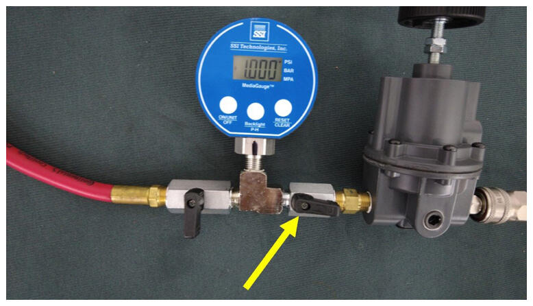
- Turn right side regulator valve to the open position.
NOTE:
By turning the valve knob to a horizontal position, The valve is fully open.
 Courtesy of TESLA, INC. Courtesy of TESLA, INC.
|
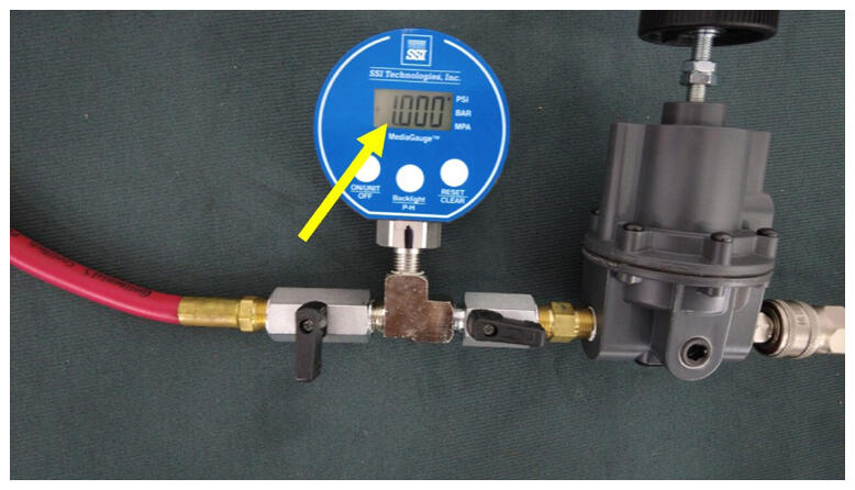
- Set regulator to 1.000 psi.
 Courtesy of TESLA, INC. Courtesy of TESLA, INC.
|
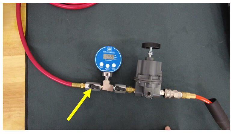
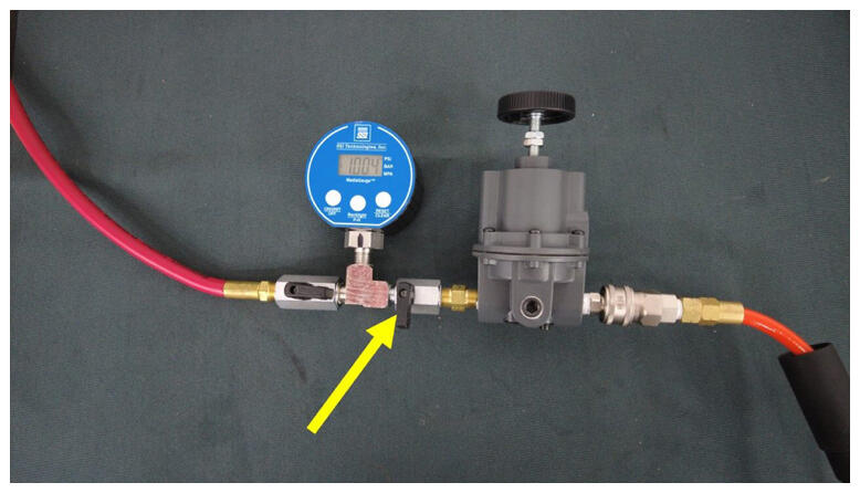
- Open the left side regulator valve to inject air into Rear Drive Inverter.
NOTE:
Close right side regulator valve when the pressure reaches 1.000 psi and stabilizes, Fill time is 60 seconds.
 Courtesy of TESLA, INC. Courtesy of TESLA, INC.
|
 Courtesy of TESLA, INC. Courtesy of TESLA, INC.
|
- Wait 60 seconds to test pressure.
 Courtesy of TESLA, INC. Courtesy of TESLA, INC.
|
- Record value of starting pressure.
 Courtesy of TESLA, INC. Courtesy of TESLA, INC.
|
- Wait 45 seconds for pressure to settle.
 Courtesy of TESLA, INC. Courtesy of TESLA, INC.
|
- Record value of end pressure.
NOTE:
Subtract the ending pressure from the starting pressure: If the difference is greater than 0.200 psi, check the hose, adapter, plug fittings, and check the regulator pressure, then retest. If the difference is still greater than 0.200 psi, escalate a Toolbox session. If the difference is 0.200 psi or less, continue the procedure.
 Courtesy of TESLA, INC. Courtesy of TESLA, INC.
|
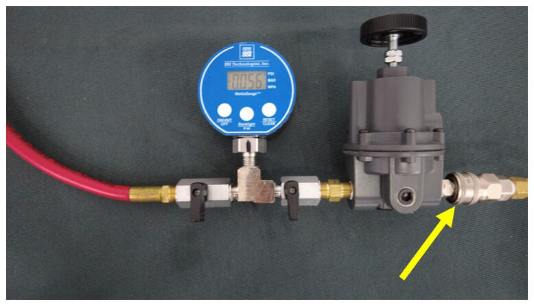
- Disconnect air supply from regulator tool.
 Courtesy of TESLA, INC. Courtesy of TESLA, INC.
|
- Disconnect leak test adapter from regulator test tool.
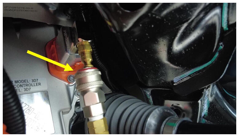 Courtesy of TESLA, INC. Courtesy of TESLA, INC.
|
- Disconnect regulator test tool from Rear Drive Inverter.
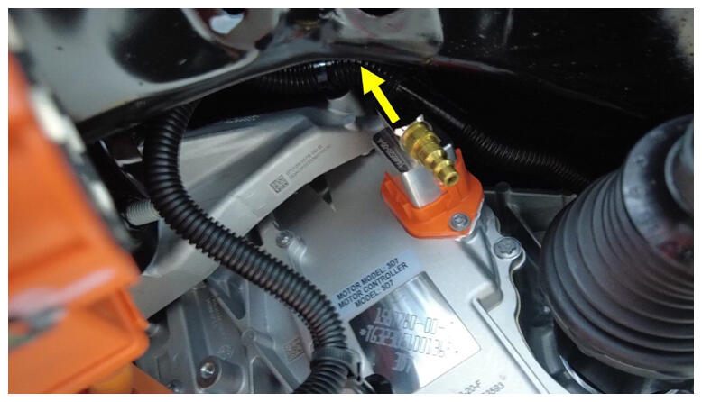 Courtesy of TESLA, INC. Courtesy of TESLA, INC.
|
- Disconnect regulator test tool from RDU logic connector.
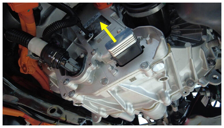 Courtesy of TESLA, INC. Courtesy of TESLA, INC.
|
- Install the 3 phase access label.
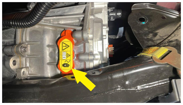 Courtesy of TESLA, INC. Courtesy of TESLA, INC.
|
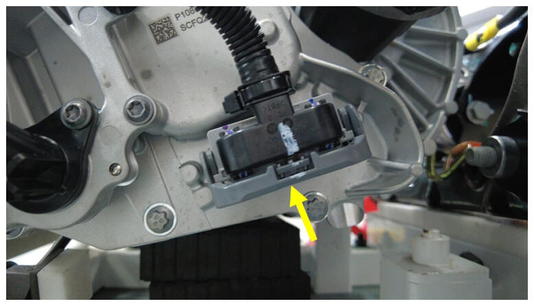
- Connect RDU logic connector.
NOTE:
1x connector, Engage locking handle.
 Courtesy of TESLA, INC. Courtesy of TESLA, INC.
|
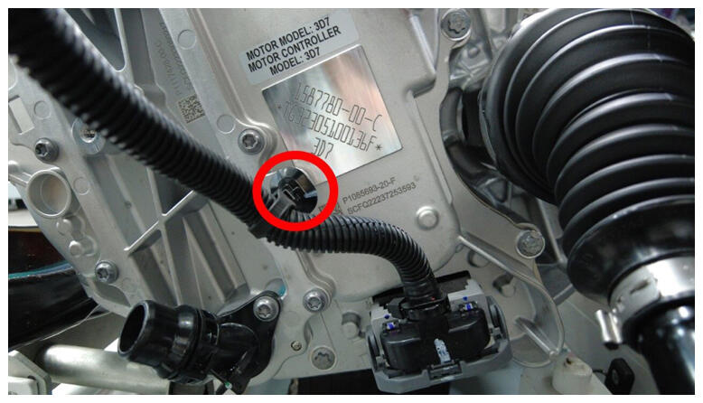
- Secure RDU logic connection clip.
NOTE:
1x clip.
 Courtesy of TESLA, INC. Courtesy of TESLA, INC.
|
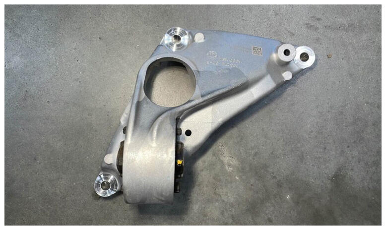
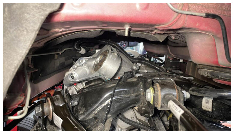
- Position LH mount assembly in between rear drive unit and subframe.
NOTE:
Maneuver between drive unit and subframe.
 Courtesy of TESLA, INC. Courtesy of TESLA, INC.
|
 Courtesy of TESLA, INC. Courtesy of TESLA, INC.
|
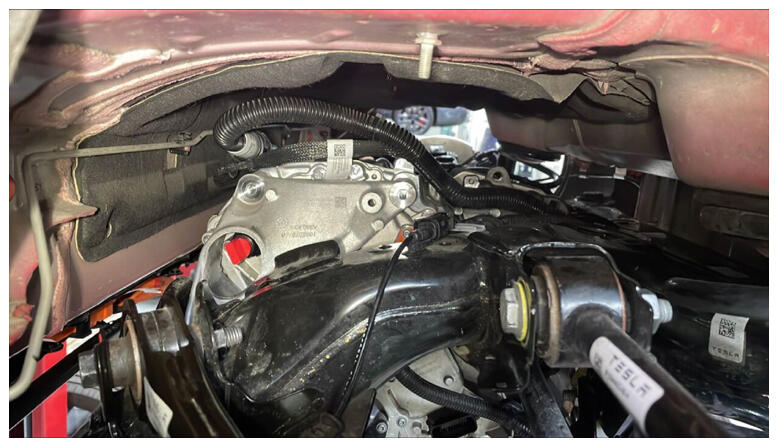 Courtesy of TESLA, INC. Courtesy of TESLA, INC.
|
- Install and torque bolts securing the LH mount assembly.
NOTE:
3x bolts, E14, 35 N.m and 55 degrees, Follow torque sequence per image.
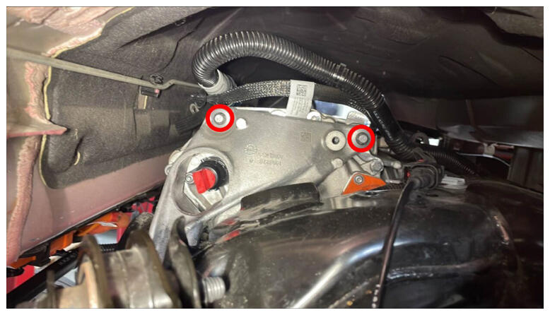 Courtesy of TESLA, INC. Courtesy of TESLA, INC.
|
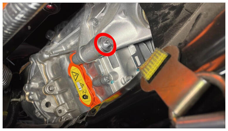 Courtesy of TESLA, INC. Courtesy of TESLA, INC.
|
- Install LH bolt securing rear drive unit to subframe.
NOTE:
1x bolt, 18 mm, 80 N.m.
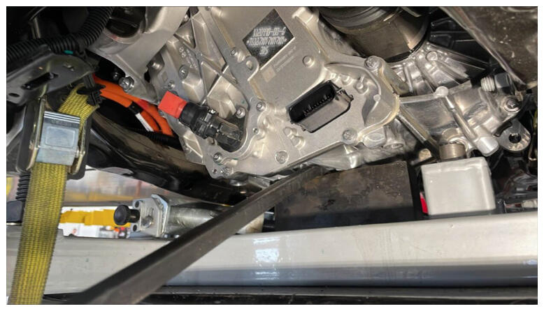 Courtesy of TESLA, INC. Courtesy of TESLA, INC.
|
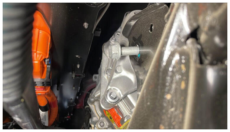 Courtesy of TESLA, INC. Courtesy of TESLA, INC.
|
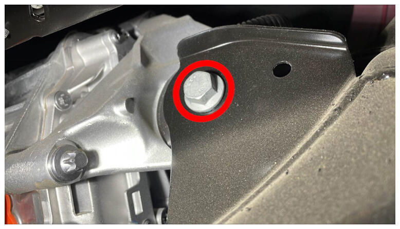 Courtesy of TESLA, INC. Courtesy of TESLA, INC.
|
- Remove center support from RDU.
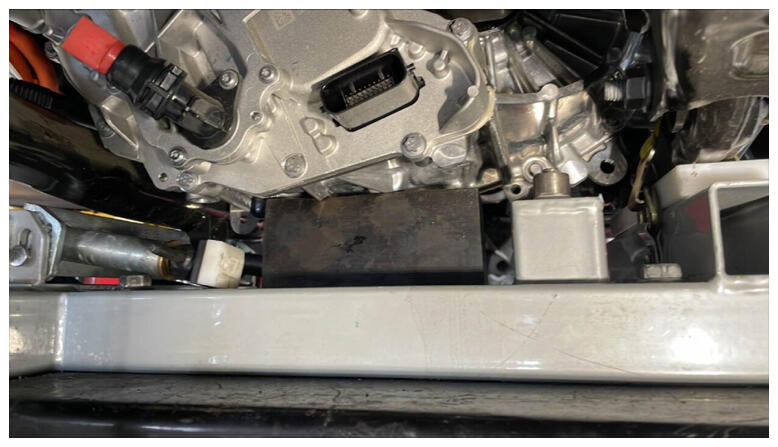 Courtesy of TESLA, INC. Courtesy of TESLA, INC.
|
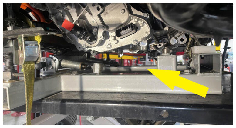 Courtesy of TESLA, INC. Courtesy of TESLA, INC.
|
- Secure inverter to cooler hose to inverter.
NOTE:
1x spring clip, Perform push-pull-push test to make sure hose is fully engaged.
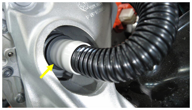 Courtesy of TESLA, INC. Courtesy of TESLA, INC.
|
- Secure inverter to cooler hose clip.
NOTE:
1x clip
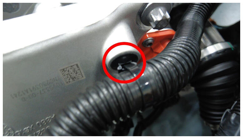 Courtesy of TESLA, INC. Courtesy of TESLA, INC.
|
- Secure RDU ground strap clip onto subframe.
NOTE:
1x clip.
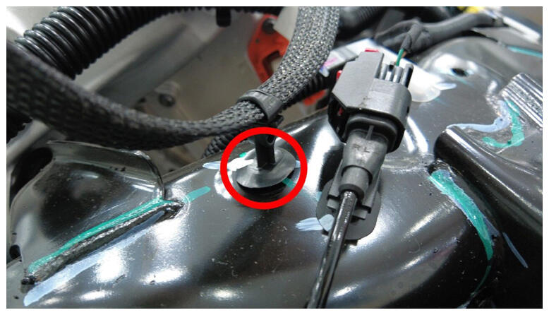 Courtesy of TESLA, INC. Courtesy of TESLA, INC.
|
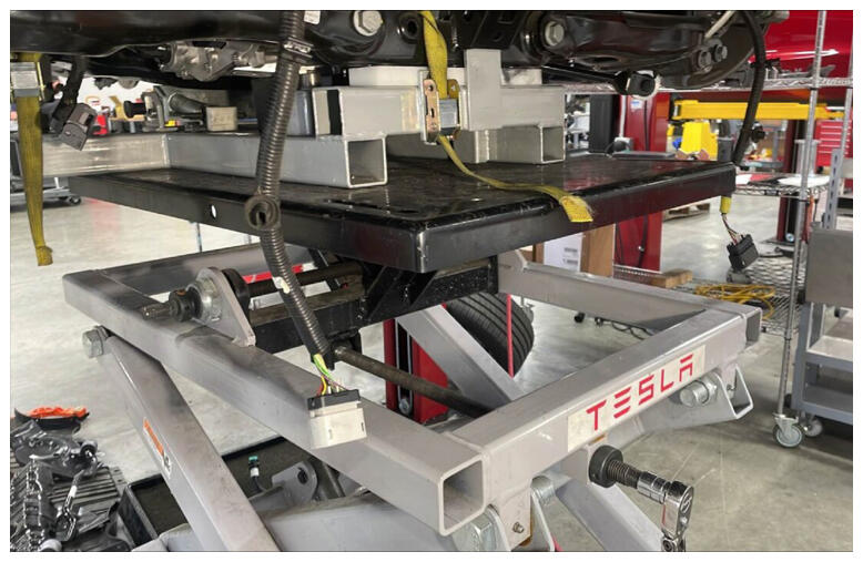
- Tilt subframe fixture backwards to original position.
NOTE:
Tilt subframe fixture back to original position.
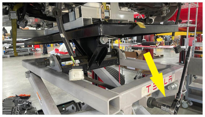 Courtesy of TESLA, INC. Courtesy of TESLA, INC.
|
 Courtesy of TESLA, INC. Courtesy of TESLA, INC.
|
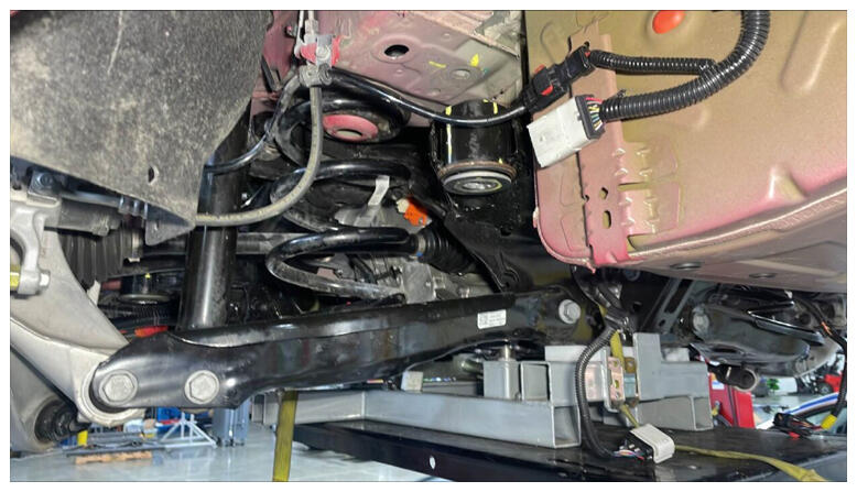
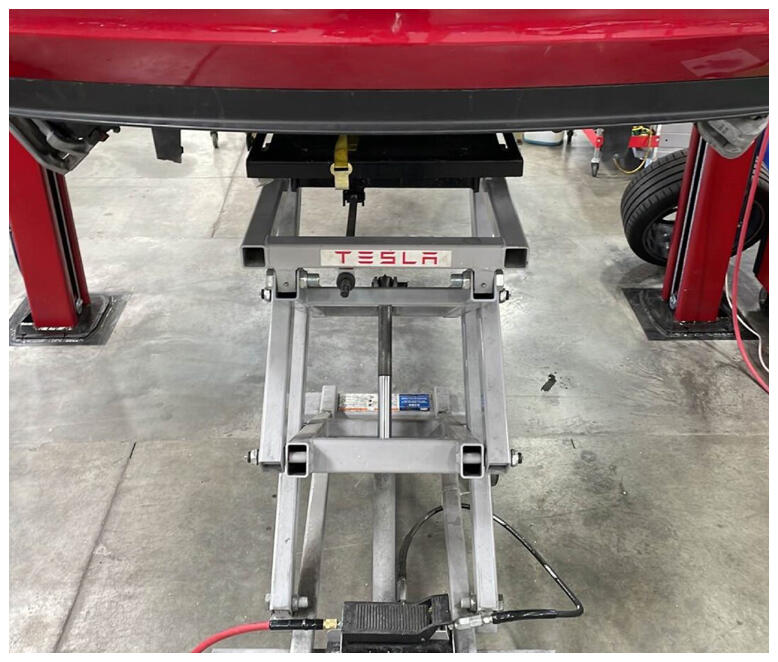
- Raise the partially lowered subframe.
NOTE:
Use caution to not damage components while raising subframe.
 Courtesy of TESLA, INC. Courtesy of TESLA, INC.
|
 Courtesy of TESLA, INC. Courtesy of TESLA, INC.
|
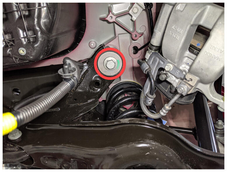
- Install RH rear bolt securing rear subframe to body hand tight.
NOTE:
1x bolt, 21 mm, 165 N.m, Install new bolt, Torque at later step.
 Courtesy of TESLA, INC. Courtesy of TESLA, INC.
|
- Install LH rear bolt securing rear subframe to body hand tight.
NOTE:
1x bolt, 21 mm, 165 N.m, Install new bolt, Torque at later step.
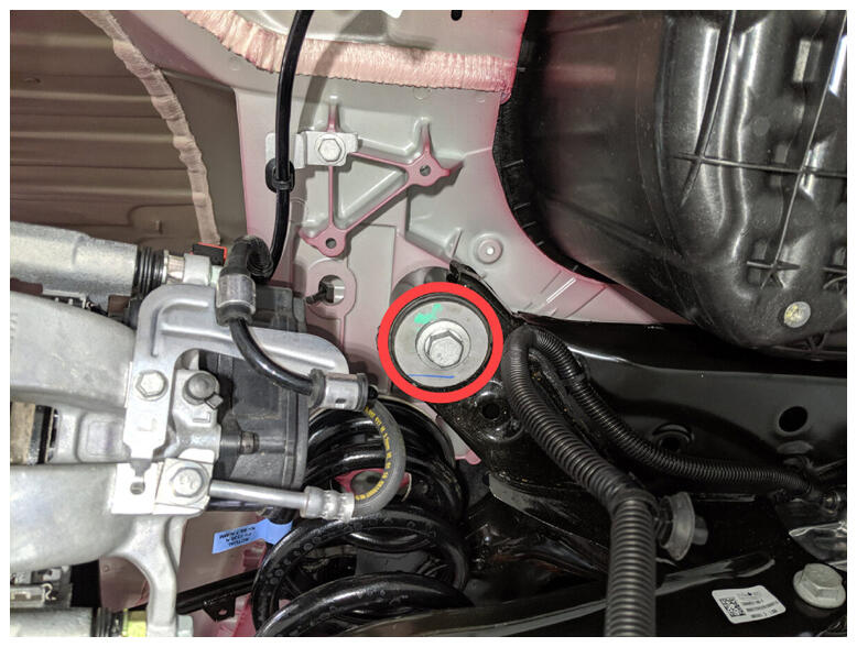 Courtesy of TESLA, INC. Courtesy of TESLA, INC.
|
- Install LH front bolt and shear plate to rear subframe hand tight.
NOTE:
1x bolt, 21 mm, 130 N.m, Install new bolt, Torque at later step.
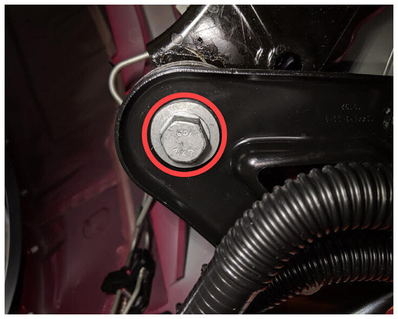 Courtesy of TESLA, INC. Courtesy of TESLA, INC.
|
- Install bolts securing LH shear plate to HV battery hand tight.
NOTE:
2x bolts, 13 mm, 35 N.m.
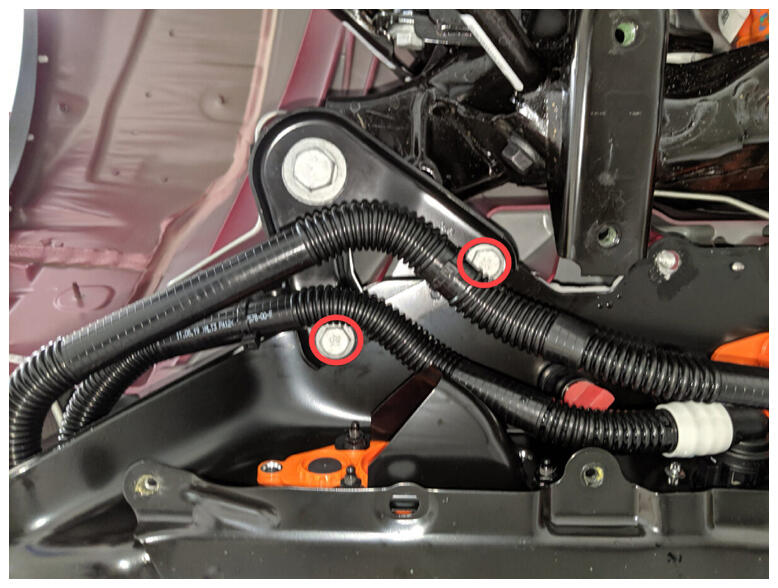 Courtesy of TESLA, INC. Courtesy of TESLA, INC.
|
- Install RH front bolt and shear plate to rear subframe hand tight.
NOTE:
1x bolt, 21 mm, 130 N.m, Install new bolt, Torque at later step.
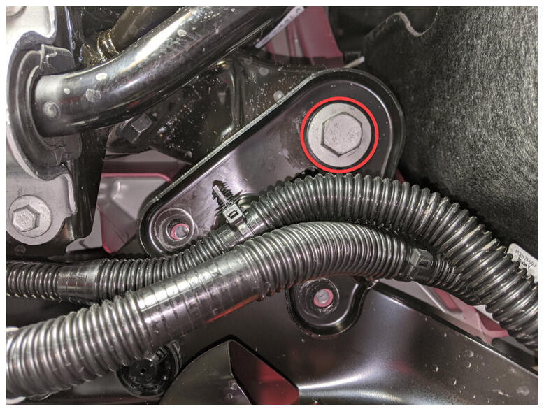 Courtesy of TESLA, INC. Courtesy of TESLA, INC.
|
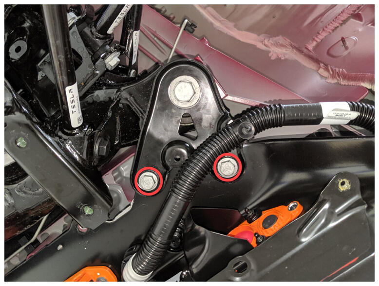
- Install bolts securing RH shear plate to HV battery hand tight.
NOTE:
2x bolts, 13 mm, 35 N.m.
 Courtesy of TESLA, INC. Courtesy of TESLA, INC.
|
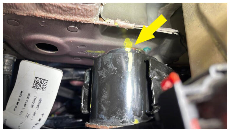
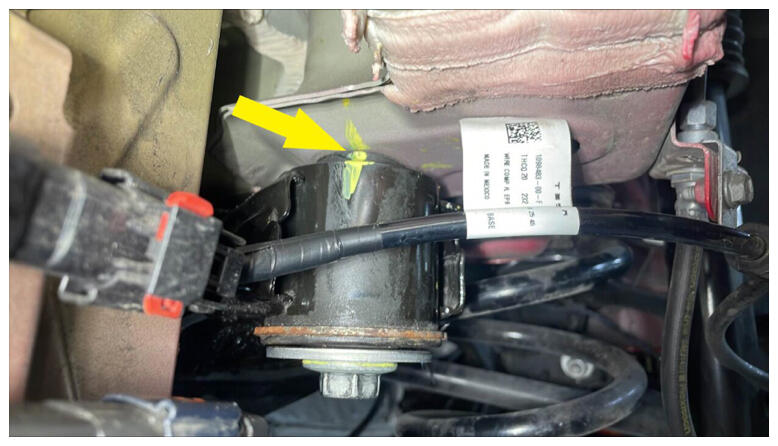
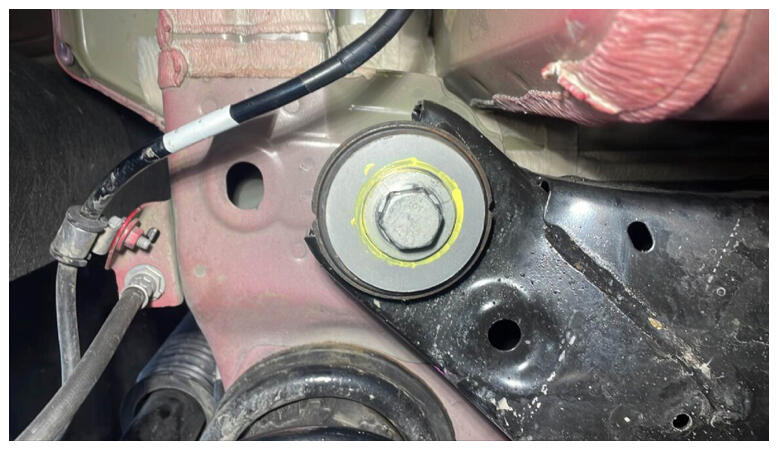
- Position subframe to marked location.
NOTE:
Use previous markings to align subframe to body, Return to original position as close as possible.
 Courtesy of TESLA, INC. Courtesy of TESLA, INC.
|
 Courtesy of TESLA, INC. Courtesy of TESLA, INC.
|
 Courtesy of TESLA, INC. Courtesy of TESLA, INC.
|
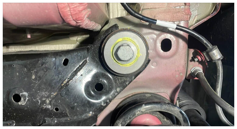 Courtesy of TESLA, INC. Courtesy of TESLA, INC.
|
- Torque bolt securing RH rear of subframe to body.
NOTE:
1x rear bolt, 21 mm, 165 N.m, Mark bolt after torque.
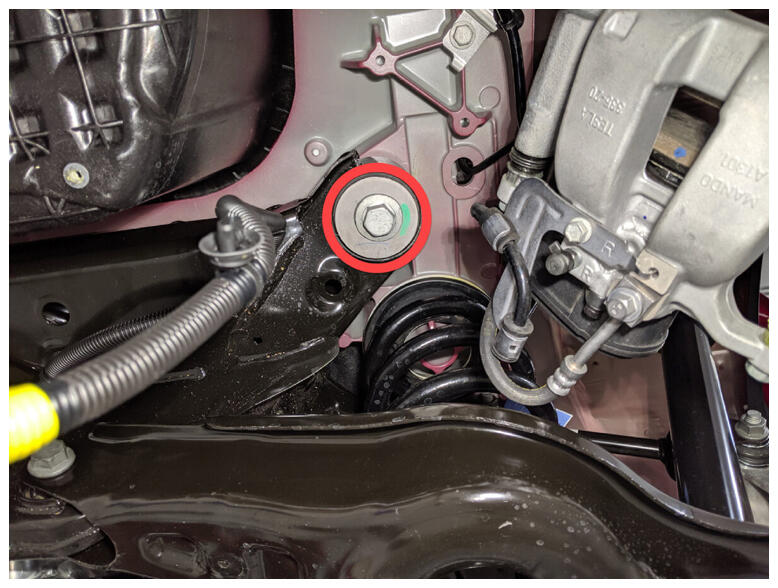 Courtesy of TESLA, INC. Courtesy of TESLA, INC.
|
- Torque bolt securing LH rear of subframe to body.
NOTE:
1x rear bolt, 21 mm, 165 N.m, Mark bolt after torque.
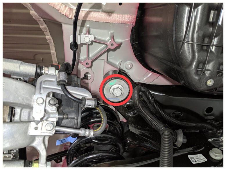 Courtesy of TESLA, INC. Courtesy of TESLA, INC.
|
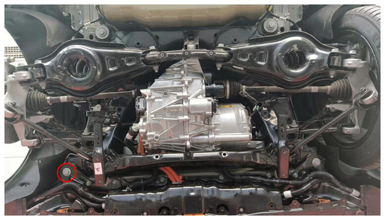
- Torque bolt securing subframe and LH shear plate to body.
NOTE:
1x front bolt, 21 mm, 130 N.m, Mark bolt after torque.
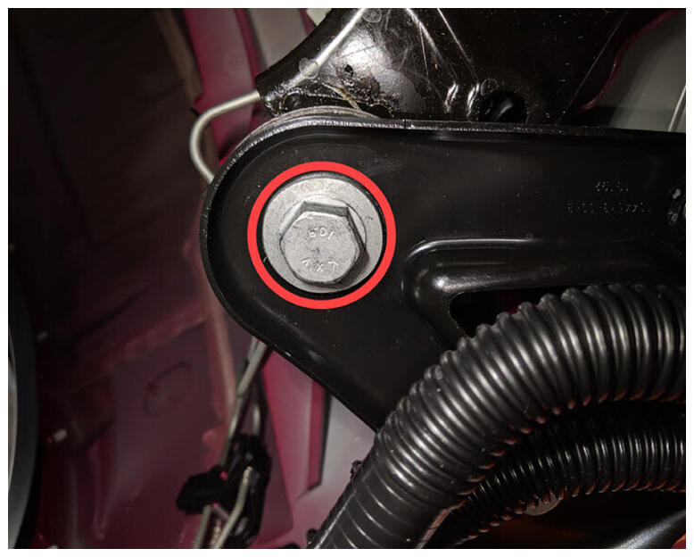 Courtesy of TESLA, INC. Courtesy of TESLA, INC.
|
 Courtesy of TESLA, INC. Courtesy of TESLA, INC.
|
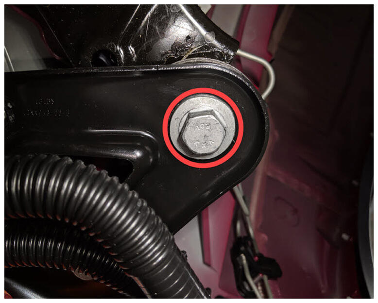
- Torque bolt securing subframe and RH shear plate to body.
NOTE:
1x front bolt, 21 mm, 130 N.m, Mark bolt after torque.
 Courtesy of TESLA, INC. Courtesy of TESLA, INC.
|
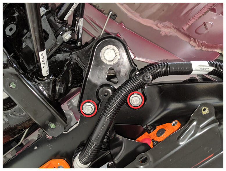
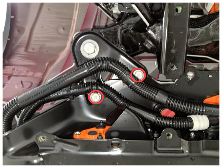
- Torque bolts securing shear plates to vehicle.
NOTE:
4x bolts, 13 mm, 35 N.m.
 Courtesy of TESLA, INC. Courtesy of TESLA, INC.
|
 Courtesy of TESLA, INC. Courtesy of TESLA, INC.
|
- Lower rear subframe lifting tool from vehicle.
NOTE:
Verify yellow safety straps are removed from subframe.
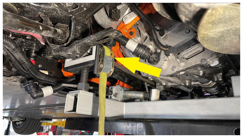 Courtesy of TESLA, INC. Courtesy of TESLA, INC.
|
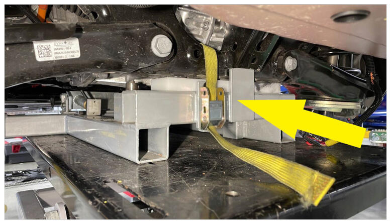 Courtesy of TESLA, INC. Courtesy of TESLA, INC.
|
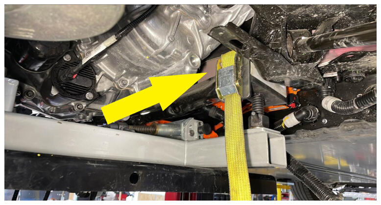 Courtesy of TESLA, INC. Courtesy of TESLA, INC.
|
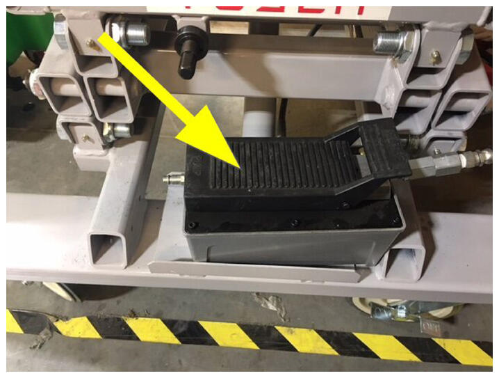 Courtesy of TESLA, INC. Courtesy of TESLA, INC.
|
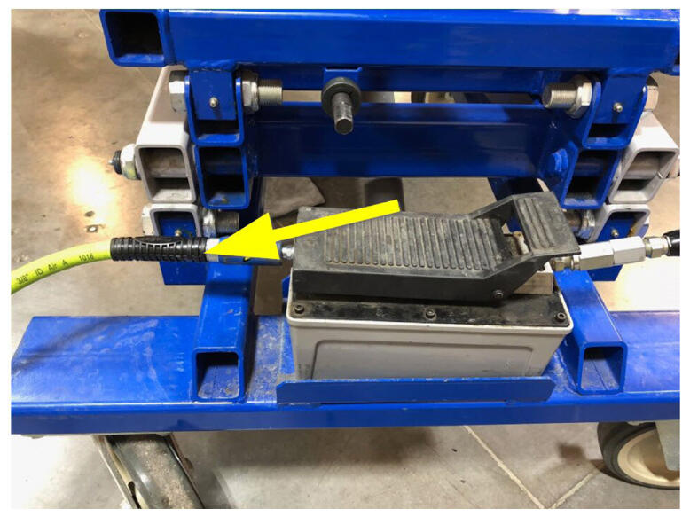
- Disconnect air supply from subframe lifting tool.
 Courtesy of TESLA, INC. Courtesy of TESLA, INC.
|
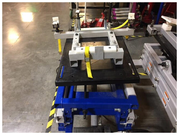
- Remove subframe lifting tool from underneath vehicle.
 Courtesy of TESLA, INC. Courtesy of TESLA, INC.
|
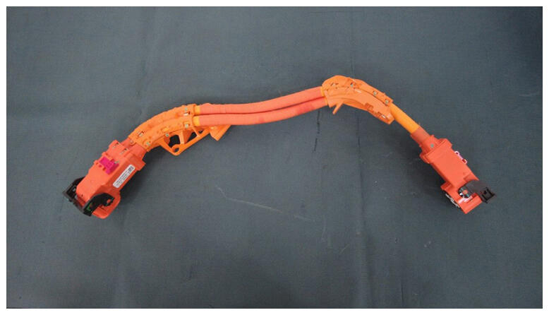
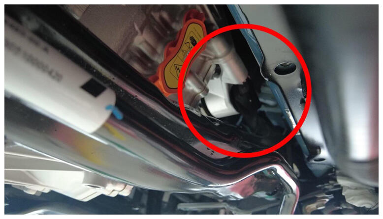
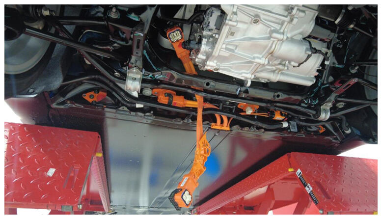
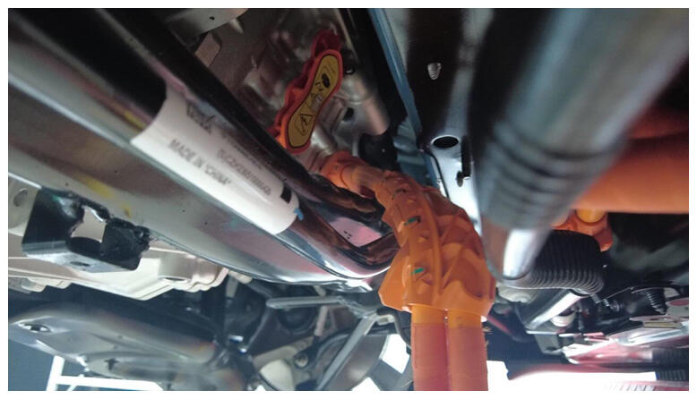
- Install RDU HV harness.
NOTE:
Route cable between rear drive unit, subframe and battery, Rotate into connection position.
 Courtesy of TESLA, INC. Courtesy of TESLA, INC.
|
 Courtesy of TESLA, INC. Courtesy of TESLA, INC.
|
 Courtesy of TESLA, INC. Courtesy of TESLA, INC.
|
 Courtesy of TESLA, INC. Courtesy of TESLA, INC.
|
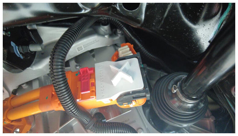
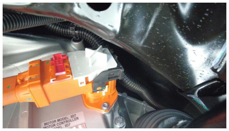
- Connect RDU HV harness to RDU.
NOTE:
1x connector, Install HV connector lever lock to RDU HV cable connector, Align connector to RDU then remove HV connector lever lock before fully latch connector, Use one hand to support the connector while other latching locking tab, Once installed, verify that the latch is not damaged and fully secured in the latched position.
 Courtesy of TESLA, INC. Courtesy of TESLA, INC.
|
 Courtesy of TESLA, INC. Courtesy of TESLA, INC.
|
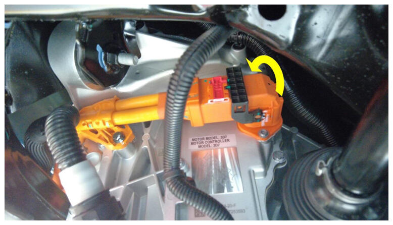 Courtesy of TESLA, INC. Courtesy of TESLA, INC.
|
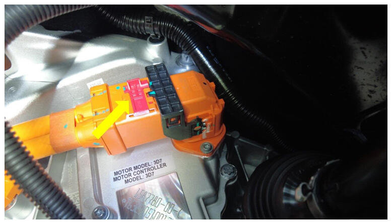 Courtesy of TESLA, INC. Courtesy of TESLA, INC.
|
- Install bolt securing RDU HV cable bracket to RDU.
NOTE:
1x location tab, 1x bolt, 10 mm, 6 N.m.
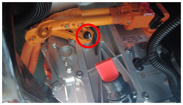 Courtesy of TESLA, INC. Courtesy of TESLA, INC.
|
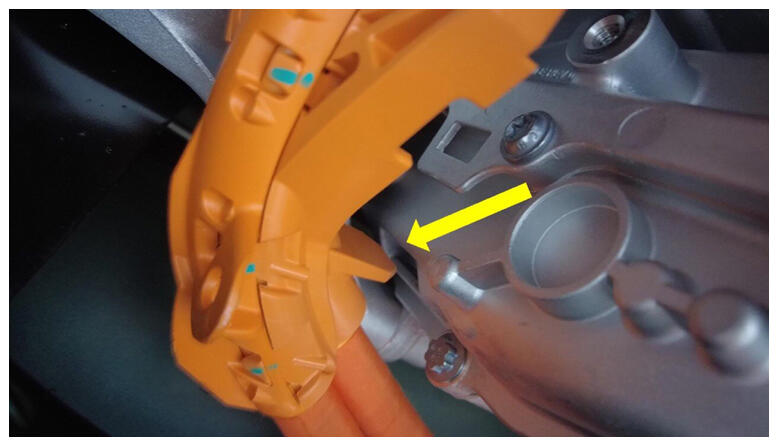 Courtesy of TESLA, INC. Courtesy of TESLA, INC.
|
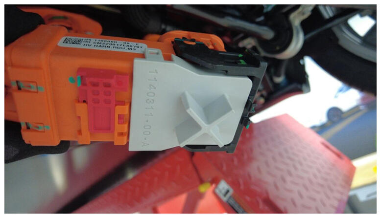
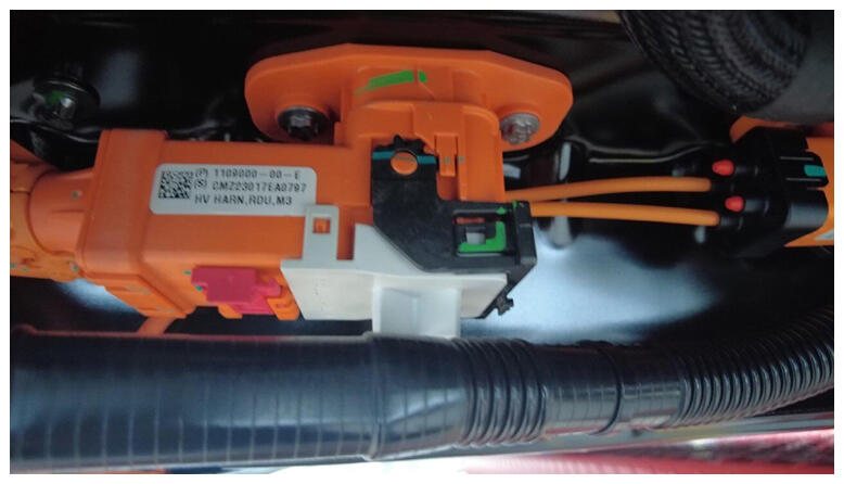
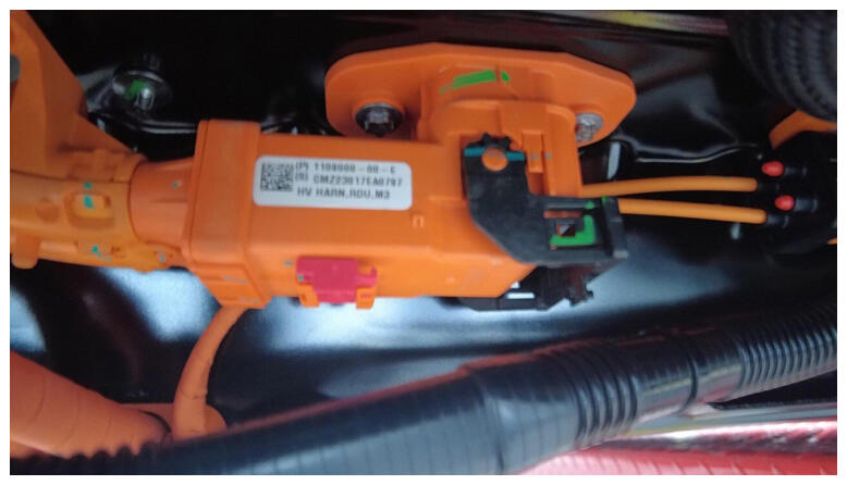
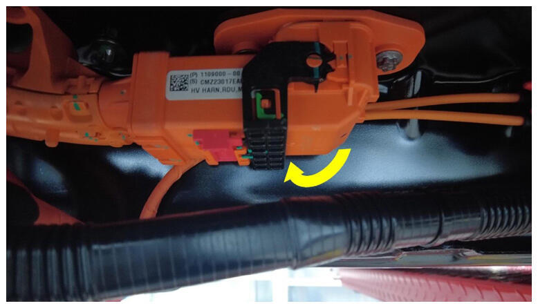
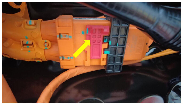
- Connect RDU HV cable to HV battery.
NOTE:
1x connector, Make sure the connector lock is 90 degrees from the connector before beginning to secure the connector, Use one hand to support the connector while other latching locking tab. Once installed, verify that the latch is not damaged and fully secured in the latched position.
 Courtesy of TESLA, INC. Courtesy of TESLA, INC.
|
 Courtesy of TESLA, INC. Courtesy of TESLA, INC.
|
 Courtesy of TESLA, INC. Courtesy of TESLA, INC.
|
 Courtesy of TESLA, INC. Courtesy of TESLA, INC.
|
 Courtesy of TESLA, INC. Courtesy of TESLA, INC.
|
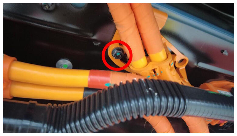
- Install nut securing RDU HV cable bracket to HV battery.
NOTE:
1x nut, 10 mm, 10 N.m, Number of fasteners may vary.
 Courtesy of TESLA, INC. Courtesy of TESLA, INC.
|
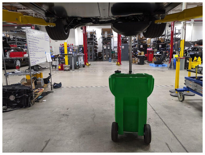
- Position coolant drain container underneath LH RDU area.
 Courtesy of TESLA, INC. Courtesy of TESLA, INC.
|
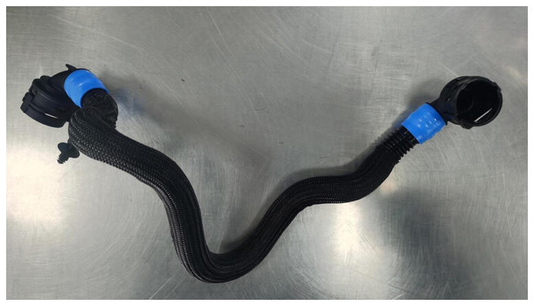
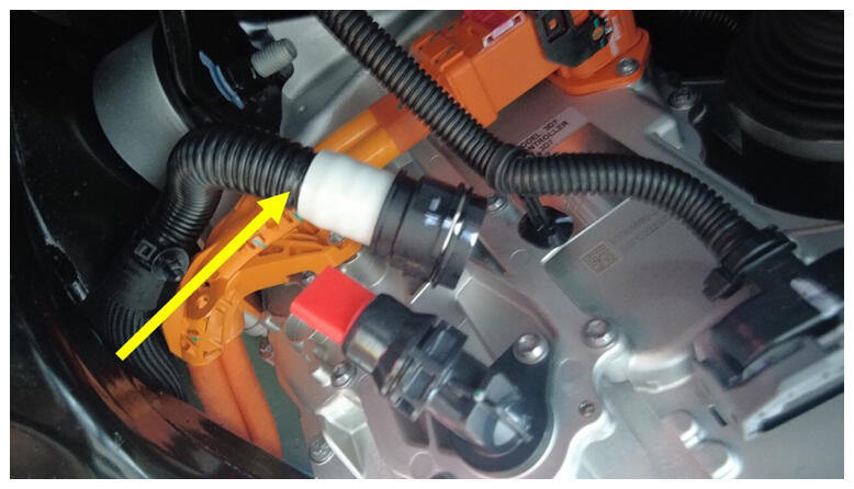
- Install RDU inverter inlet tube into subframe.
NOTE:
Maneuver hose as needed to position between rear subframe and RDU HV cable harness.
 Courtesy of TESLA, INC. Courtesy of TESLA, INC.
|
 Courtesy of TESLA, INC. Courtesy of TESLA, INC.
|
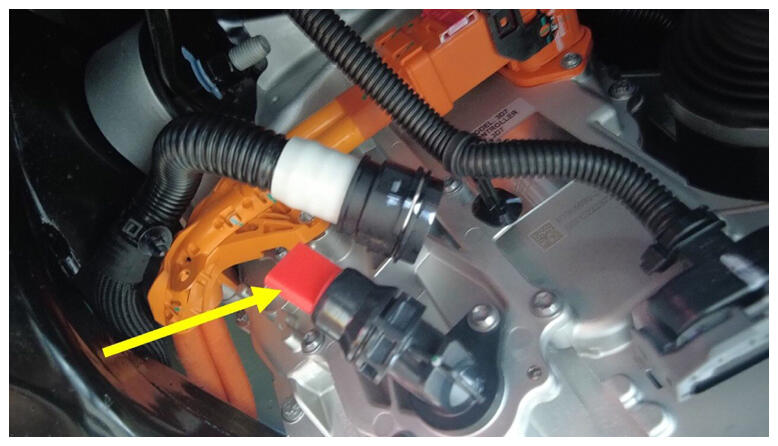
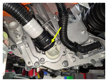
- Remove plug from fluid coupling and connect RDU inverter inlet tube.
NOTE:
1x spring clip, 1x plug, Perform push-pull-push test to make sure hose is fully engaged.
 Courtesy of TESLA, INC. Courtesy of TESLA, INC.
|
 Courtesy of TESLA, INC. Courtesy of TESLA, INC.
|
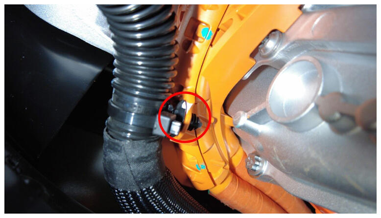
- Secure RDU inverter inlet tube onto RDU HV cable harness.
NOTE:
1x fir tree clip.
 Courtesy of TESLA, INC. Courtesy of TESLA, INC.
|
- Position coolant drain container underneath LH rear of HV battery.
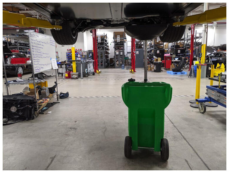 Courtesy of TESLA, INC. Courtesy of TESLA, INC.
|
- Remove plug from HV battery and connect RDU inverter inlet tube.
NOTE:
1x spring clip, 1x plug, Perform push-pull-push test to make sure hose is fully engaged.
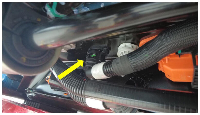 Courtesy of TESLA, INC. Courtesy of TESLA, INC.
|
- Remove coolant drain container from underneath vehicle.
- Position HV battery rear skid plate enclosure onto HV battery for installation.
NOTE:
Recommend assistance if needed.
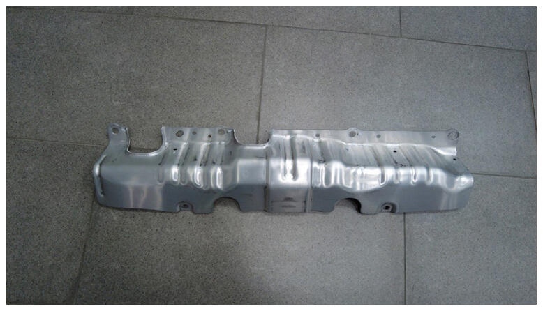 Courtesy of TESLA, INC. Courtesy of TESLA, INC.
|
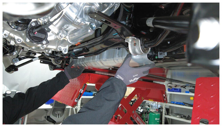 Courtesy of TESLA, INC. Courtesy of TESLA, INC.
|
- Install upper bolts securing HV battery rear skid plate enclosure hand tight.
NOTE:
4x bolts, 13 mm, 35 N.m, Torque at later step.
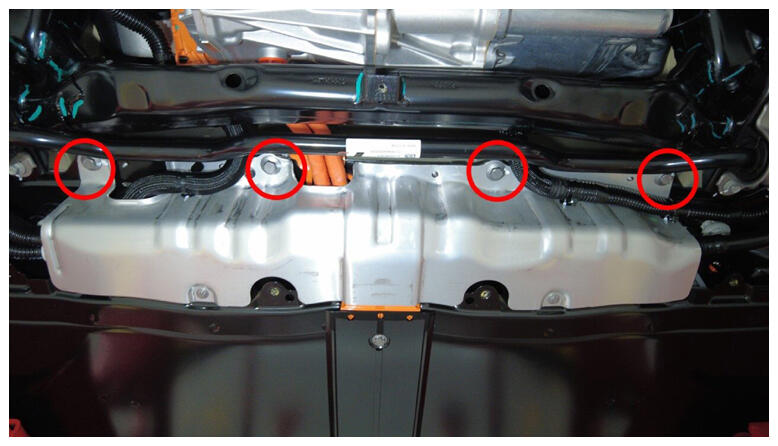 Courtesy of TESLA, INC. Courtesy of TESLA, INC.
|
- Install upper nut securing HV battery rear skid plate enclosure hand tight.
NOTE:
1x nut, 10 mm, 13 N.m, Torque at later step.
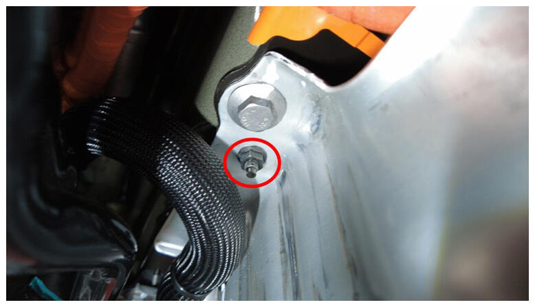 Courtesy of TESLA, INC. Courtesy of TESLA, INC.
|
- Install lower bolts securing HV battery rear skid plate enclosure.
NOTE:
2x bolts, EP10, 13 N.m, Earlier vins may be equipped with additional bolts.
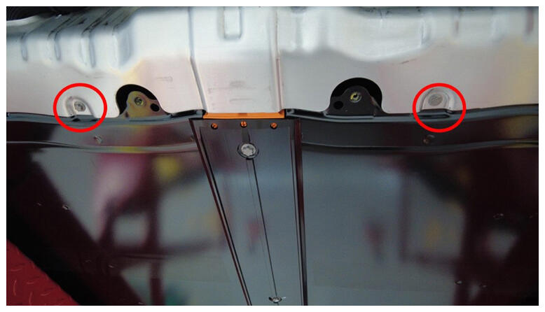 Courtesy of TESLA, INC. Courtesy of TESLA, INC.
|
- Torque bolts securing HV battery rear skid plate enclosure to vehicle.
NOTE:
4x bolts, 13 mm, 35 N.m.
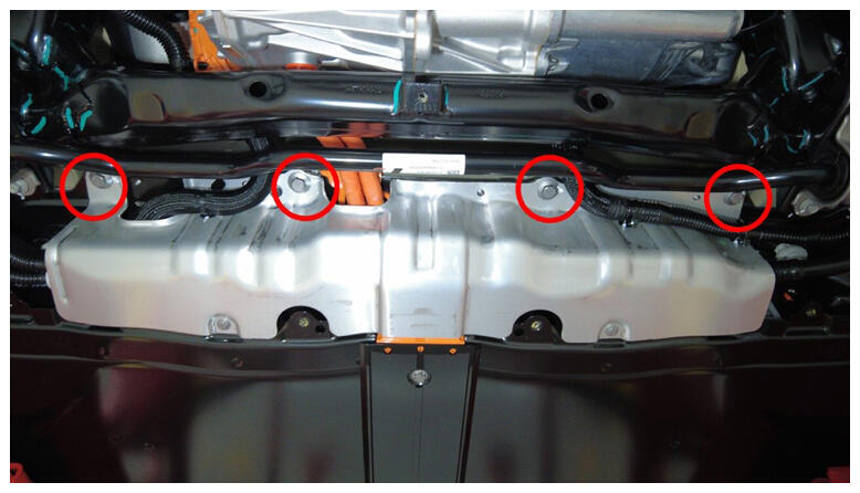 Courtesy of TESLA, INC. Courtesy of TESLA, INC.
|
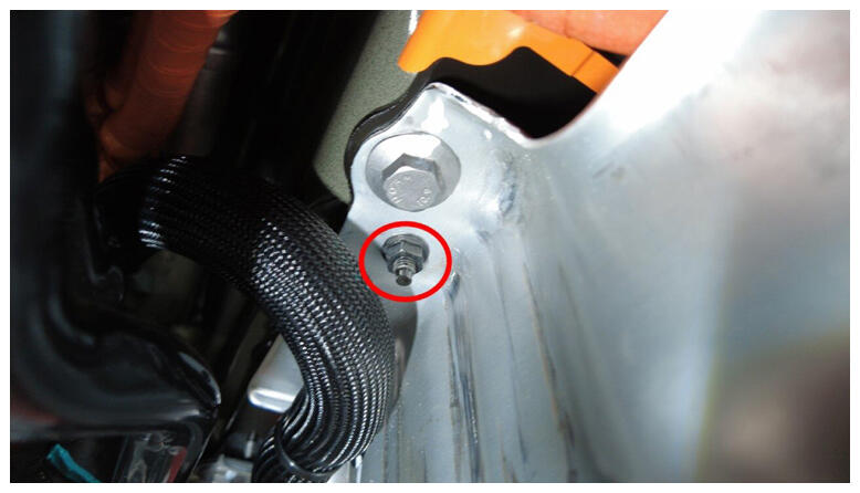
- Torque upper nut securing HV battery rear skid plate enclosure.
NOTE:
1x nut, 10 mm, 13 N.m.
 Courtesy of TESLA, INC. Courtesy of TESLA, INC.
|
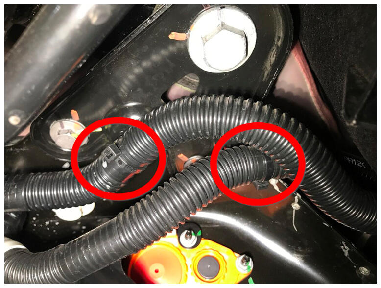
- Install clips securing coolant hoses to RH shear plate.
NOTE:
2x fir tree clips.
 Courtesy of TESLA, INC. Courtesy of TESLA, INC.
|
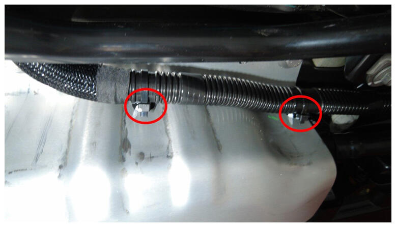
- Install RH side hose clips to HV battery rear skid plate enclosure.
NOTE:
2x fir tree clips.
 Courtesy of TESLA, INC. Courtesy of TESLA, INC.
|
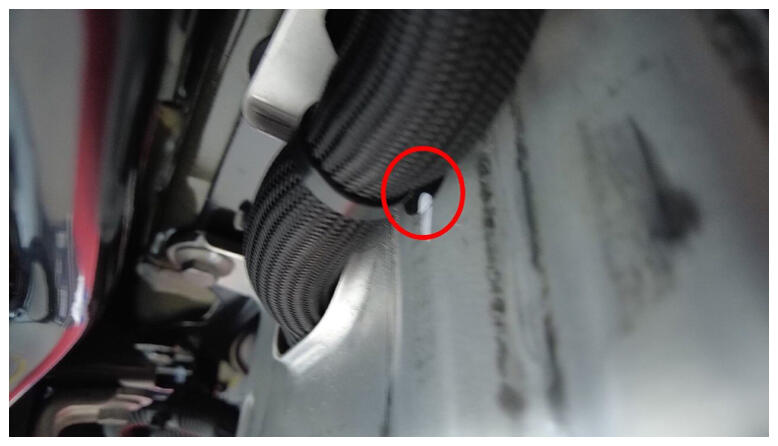
- Install LH side hose clip to HV battery rear skid plate enclosure.
NOTE:
1x clip.
 Courtesy of TESLA, INC. Courtesy of TESLA, INC.
|
- Install clips securing coolant hoses to LH shear plate.
NOTE:
2x fir tree clips.
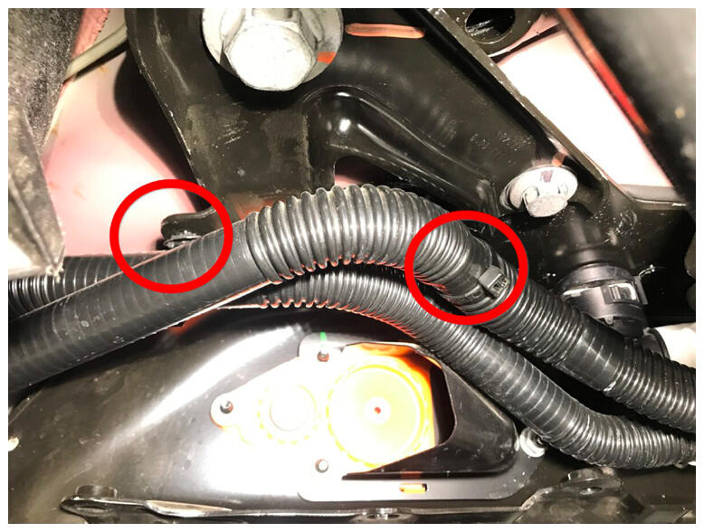 Courtesy of TESLA, INC. Courtesy of TESLA, INC.
|
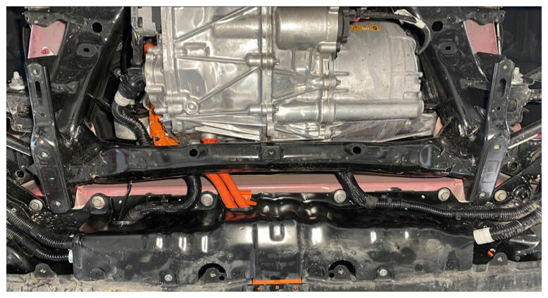
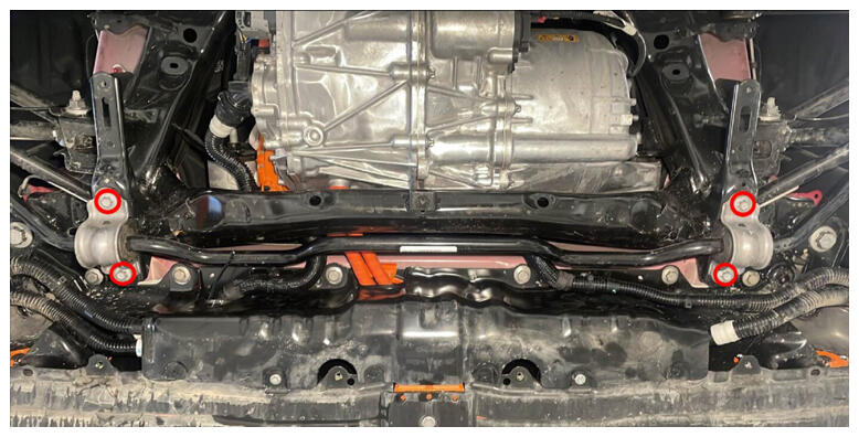
- Position rear stabilizer bar into vehicle and install fasteners.
NOTE:
4x patch bolts, 11 mm, 30 N.m, Position rear stabilizer bar into vehicle, Thread in fasteners and torque down evenly, Install new patch bolts.
 Courtesy of TESLA, INC. Courtesy of TESLA, INC.
|
 Courtesy of TESLA, INC. Courtesy of TESLA, INC.
|
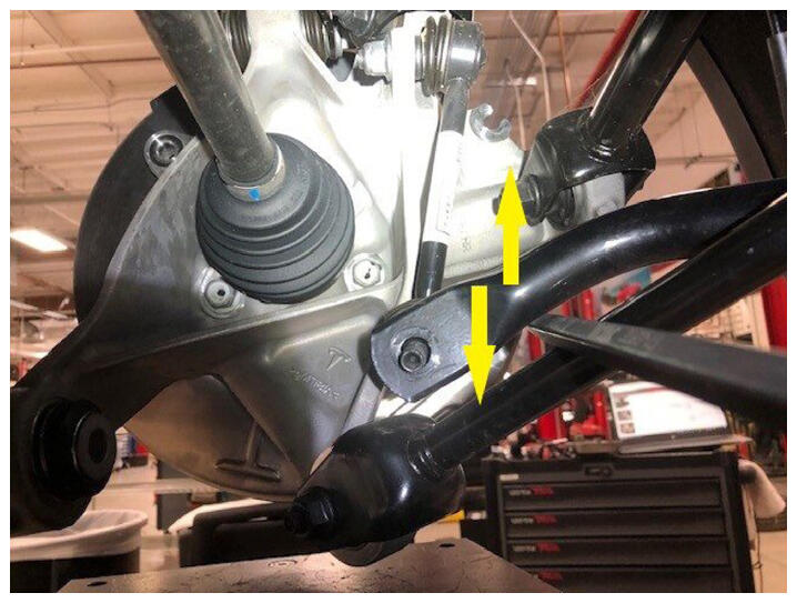
- Position LH rear end link into stabilizer bar.
NOTE:
Adjust the end link to align with stabilizer bar, Also may need to move the stabilizer bar up/down to get the correct angle to install end link.
 Courtesy of TESLA, INC. Courtesy of TESLA, INC.
|
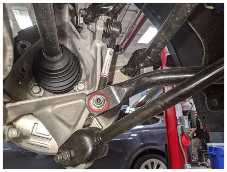
- Install nut securing LH rear end link to stabilizer bar.
NOTE:
1x nyloc nut, 15 mm, 55 N.m, Counter-hold ball joint with 5 mm hex, Install new nyloc nut, Mark bolt after torque.
 Courtesy of TESLA, INC. Courtesy of TESLA, INC.
|
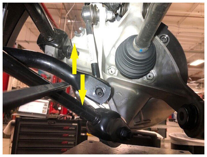
- Position RH rear end link into stabilizer bar.
NOTE:
Adjust the end link to align with stabilizer bar, Also may need to move the stabilizer bar up/down to get the correct angle to install end link.
 Courtesy of TESLA, INC. Courtesy of TESLA, INC.
|
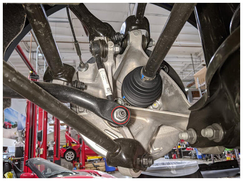
- Install nut securing RH rear end link to stabilizer bar.
NOTE:
1x nyloc nut, 15 mm, 55 N.m, Counter-hold ball joint with 5 mm hex, Install new nyloc nut, Mark bolt after torque.
 Courtesy of TESLA, INC. Courtesy of TESLA, INC.
|
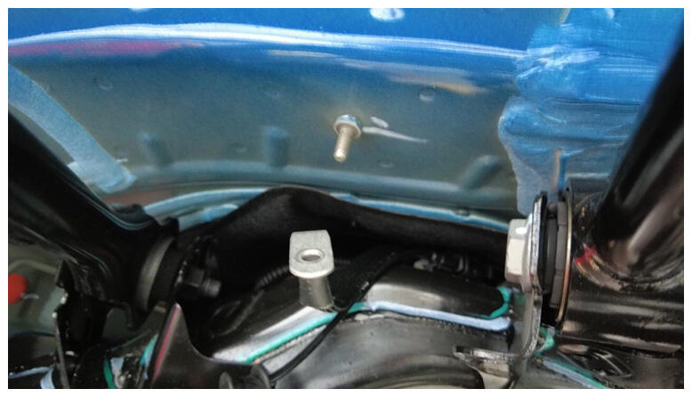
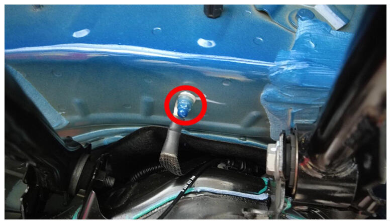
- Install RDU ground strap.
NOTE:
1x bolt, 10 mm, 10 N.m, Re-install 1x washer if vehicle had this washer during removal, Located at LH rear wheel well area.
 Courtesy of TESLA, INC. Courtesy of TESLA, INC.
|
 Courtesy of TESLA, INC. Courtesy of TESLA, INC.
|
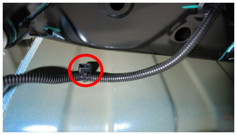
- Install RH side subframe harness clip to body.
NOTE:
1x barrel clip.
 Courtesy of TESLA, INC. Courtesy of TESLA, INC.
|
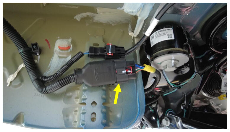
- Connect RH side subframe harness connector.
NOTE:
1x connector.
 Courtesy of TESLA, INC. Courtesy of TESLA, INC.
|
- Lower vehicle partially and set lift onto locks.
NOTE:
Raise lift off locks, then hold lock release lever to keep locks free while vehicle is lowered, Set vehicle to comfortable working height.
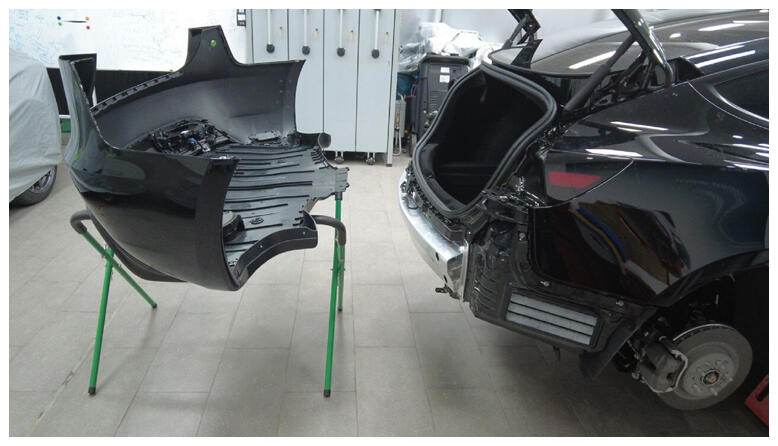
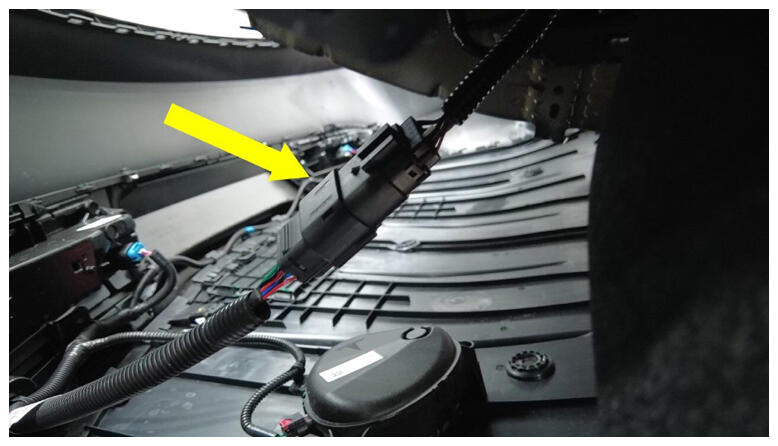
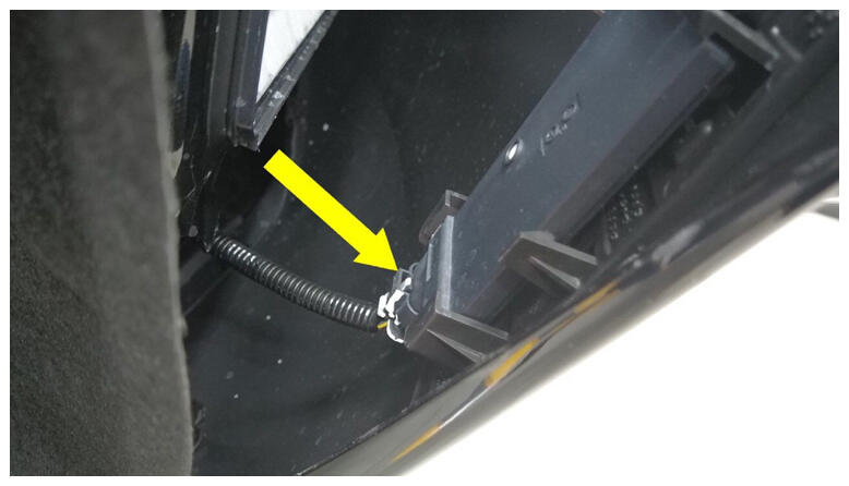
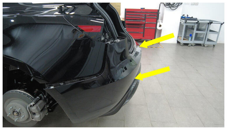
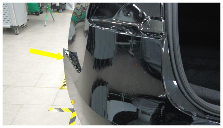
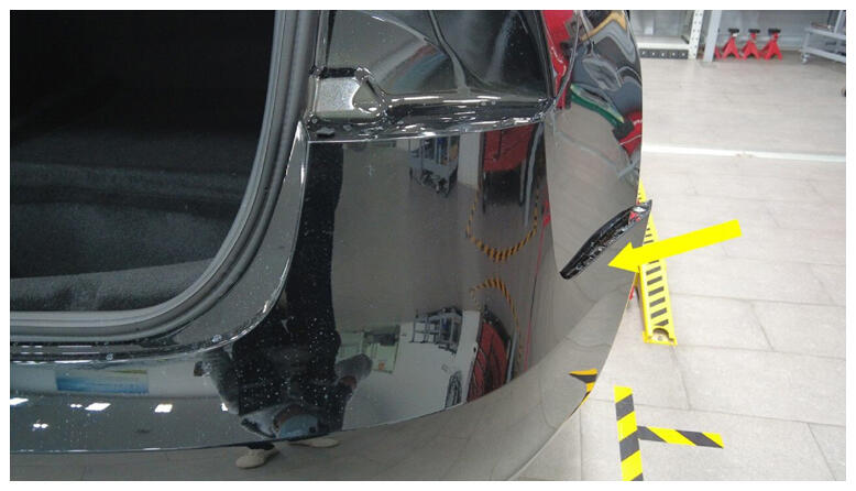
- Install rear fascia.
NOTE:
2x connector, Recommend assistance.
 Courtesy of TESLA, INC. Courtesy of TESLA, INC.
|
 Courtesy of TESLA, INC. Courtesy of TESLA, INC.
|
 Courtesy of TESLA, INC. Courtesy of TESLA, INC.
|
 Courtesy of TESLA, INC. Courtesy of TESLA, INC.
|
 Courtesy of TESLA, INC. Courtesy of TESLA, INC.
|
 Courtesy of TESLA, INC. Courtesy of TESLA, INC.
|
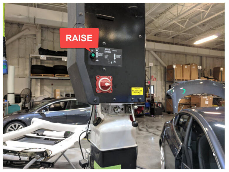
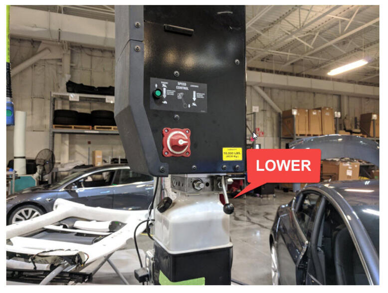
- Raise vehicle fully and lower lift onto locks.
NOTE:
Set vehicle to comfortable working height, Make sure there's an audible click of locks on both sides before lowering, otherwise vehicle may tilt to side.
 Courtesy of TESLA, INC. Courtesy of TESLA, INC.
|
 Courtesy of TESLA, INC. Courtesy of TESLA, INC.
|
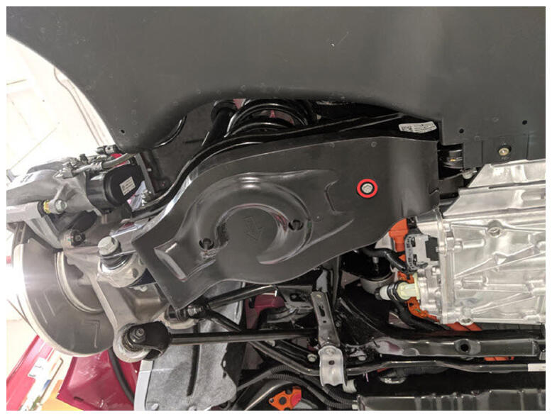
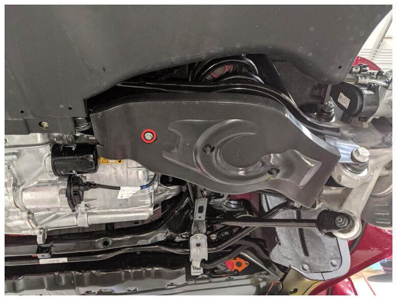
- Install LH rear suspension cover.
NOTE:
1x bolt, 10 mm, 6 N.m, 2x tabs.
 Courtesy of TESLA, INC. Courtesy of TESLA, INC.
|
- Install RH rear suspension cover.
NOTE:
1x bolt, 10 mm, 6 N.m, 2x tabs.
 Courtesy of TESLA, INC. Courtesy of TESLA, INC.
|
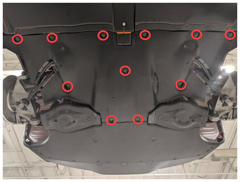
- Install rear aero shield.
NOTE:
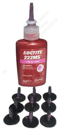
11x bolts, 10 mm, 5 N.m, Apply Loctite 222 onto rear aero shield bolts.
 Courtesy of TESLA, INC. Courtesy of TESLA, INC.
|
 Courtesy of TESLA, INC. Courtesy of TESLA, INC.
|
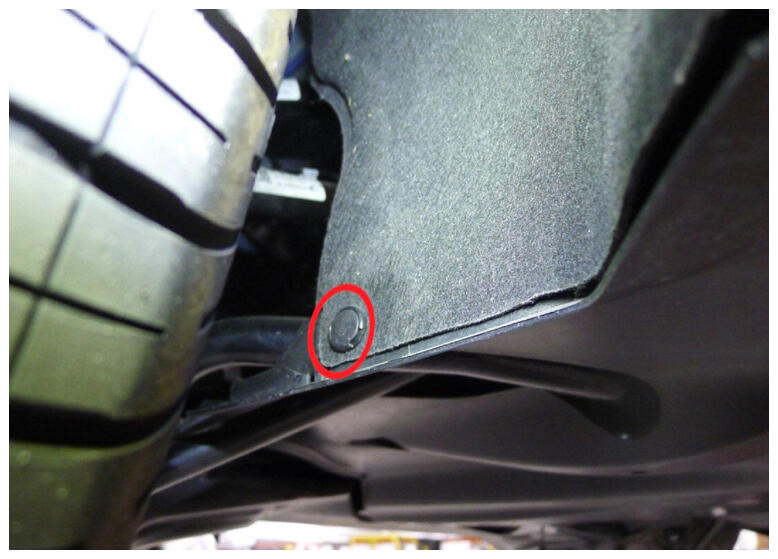
- Install LH and RH clips securing rear aero shield to wheel house liner.
NOTE:
2x clips.
 Courtesy of TESLA, INC. Courtesy of TESLA, INC.
|
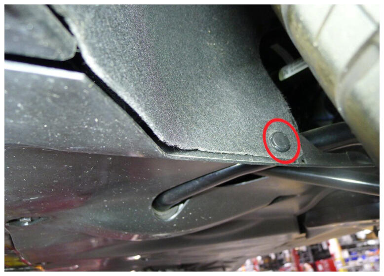 Courtesy of TESLA, INC. Courtesy of TESLA, INC.
|
- Apply Loctite 222 onto bolts and install bolts securing rear diffuser to body.
NOTE:
4x bolts, 10 mm, 4 N.m, 2x fastener covers.
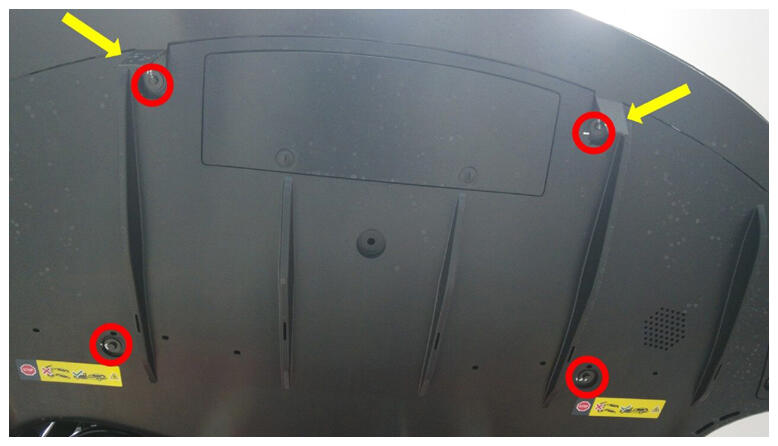 Courtesy of TESLA, INC. Courtesy of TESLA, INC.
|
- Lower vehicle partially and set onto locks.
NOTE:
Raise lift off locks, then hold lock release lever to keep locks free while vehicle is lowered, Set vehicle to comfortable working height.
- Install screw securing rear fascia to LH quarter panel.
NOTE:
1x screw, T25, 2 N.m.
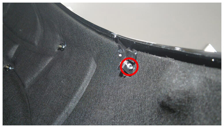 Courtesy of TESLA, INC. Courtesy of TESLA, INC.
|
- Install screw securing rear fascia to RH quarter panel.
NOTE:
1x screw, T25, 2 N.m.
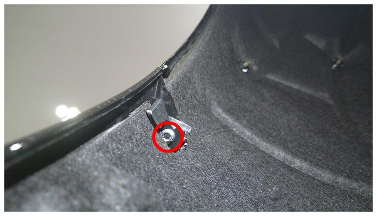 Courtesy of TESLA, INC. Courtesy of TESLA, INC.
|
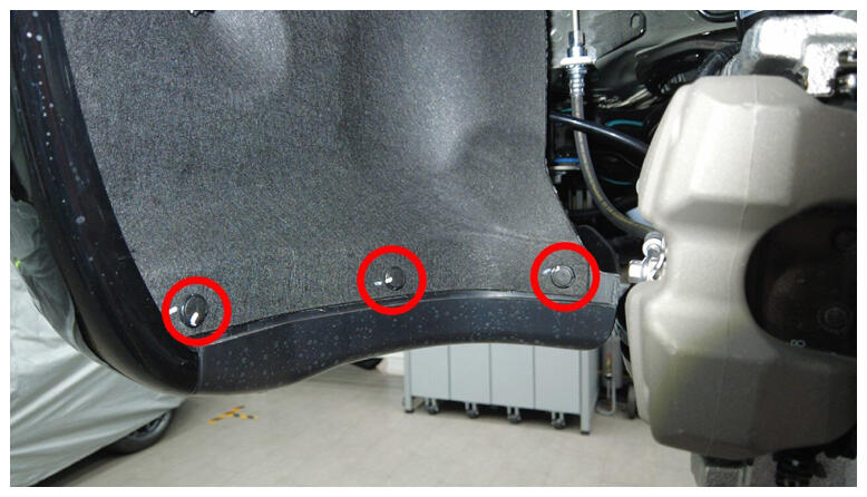
- Install lower clips securing RH rear wheel liner.
NOTE:
3x push clips.
 Courtesy of TESLA, INC. Courtesy of TESLA, INC.
|
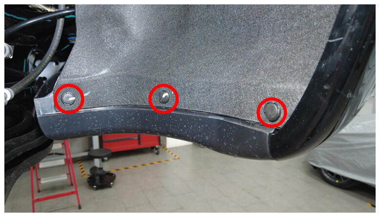
- Install lower clips securing LH rear wheel liner.
NOTE:
3x push clips.
 Courtesy of TESLA, INC. Courtesy of TESLA, INC.
|
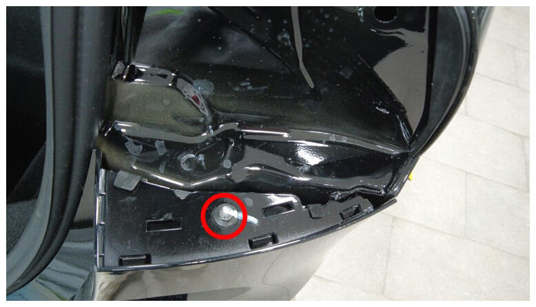
- Install bolt securing RH corner of rear fascia.
NOTE:
1x bolt, 10 mm, 4 N.m.
 Courtesy of TESLA, INC. Courtesy of TESLA, INC.
|
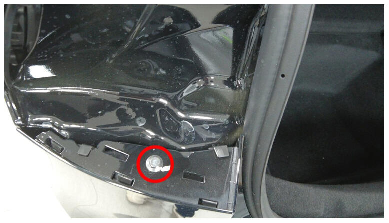
- Install bolt securing LH corner of rear fascia.
NOTE:
1x bolt, 10 mm, 4 N.m.
 Courtesy of TESLA, INC. Courtesy of TESLA, INC.
|
- Install RH trough trim.
NOTE:
3x clips, 1x bolt, T20, 1.2 N.m.
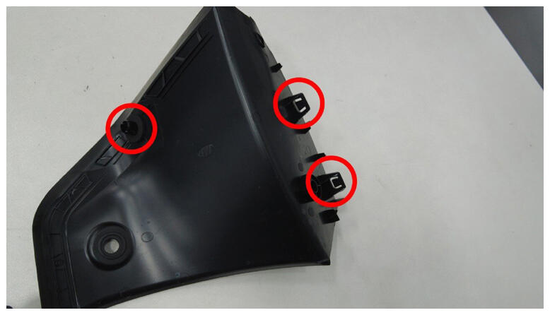 Courtesy of TESLA, INC. Courtesy of TESLA, INC.
|
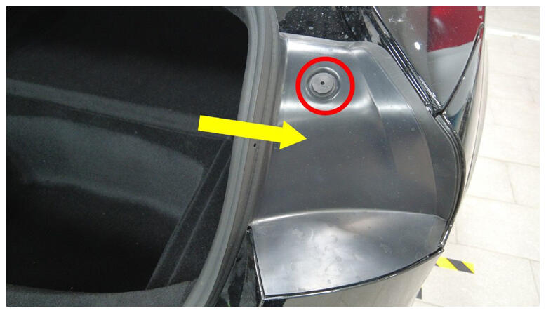 Courtesy of TESLA, INC. Courtesy of TESLA, INC.
|
- Install LH trough trim.
NOTE:
3x clips, 1x bolt, T20, 1.2 N.m.
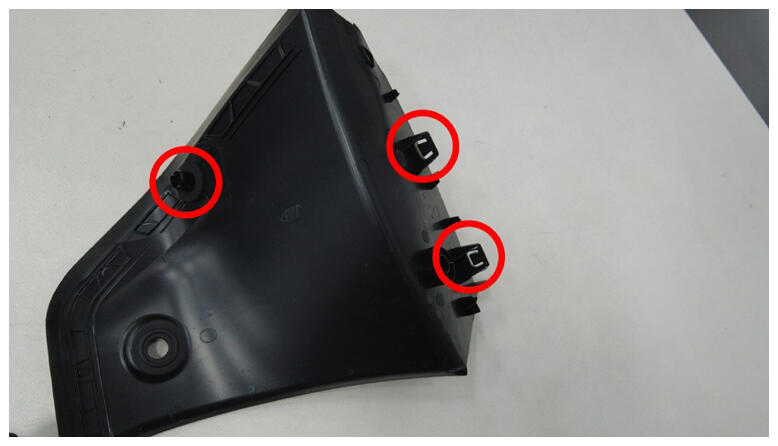 Courtesy of TESLA, INC. Courtesy of TESLA, INC.
|
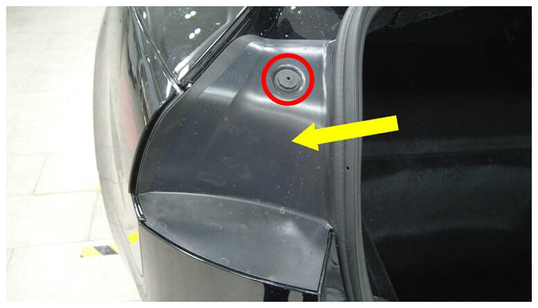 Courtesy of TESLA, INC. Courtesy of TESLA, INC.
|
- Close trunk via interior switch.
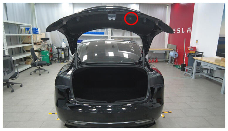 Courtesy of TESLA, INC. Courtesy of TESLA, INC.
|
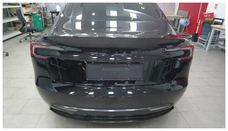 Courtesy of TESLA, INC. Courtesy of TESLA, INC.
|
- Remove coolant bottle cap.
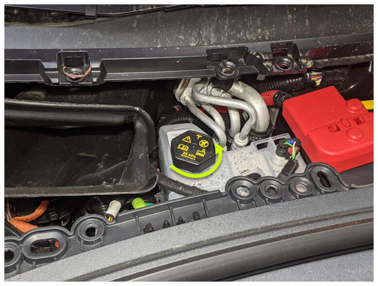 Courtesy of TESLA, INC. Courtesy of TESLA, INC.
|
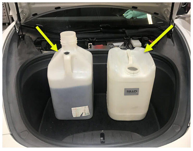
- Place empty coolant container into front storage area.
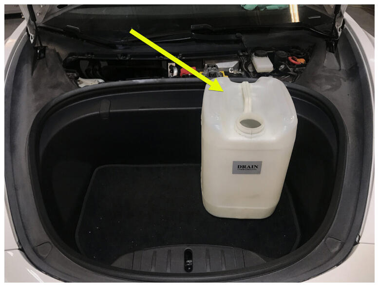 Courtesy of TESLA, INC. Courtesy of TESLA, INC.
|
- Fill container with at least 15L of coolant.
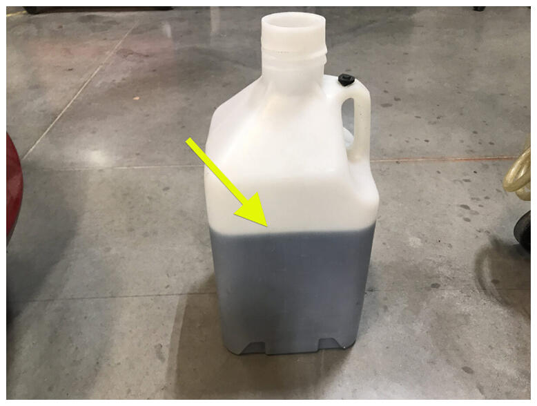 Courtesy of TESLA, INC. Courtesy of TESLA, INC.
|
- Place filled coolant container into front storage area.
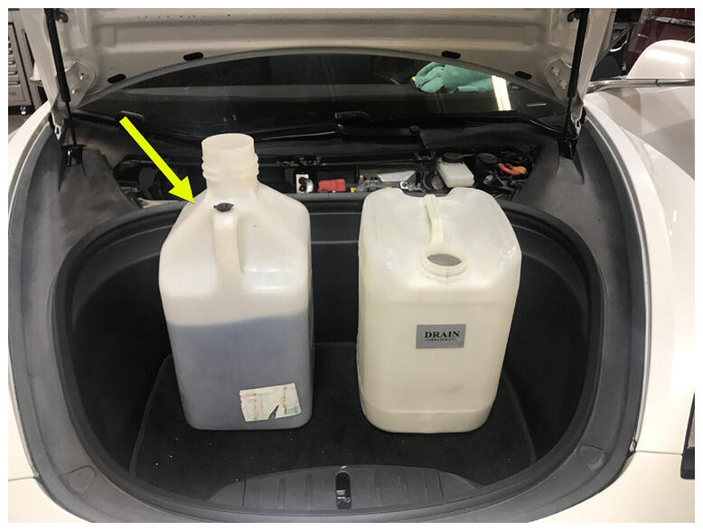 Courtesy of TESLA, INC. Courtesy of TESLA, INC.
|
- Install refill tool cap onto coolant bottle assembly.
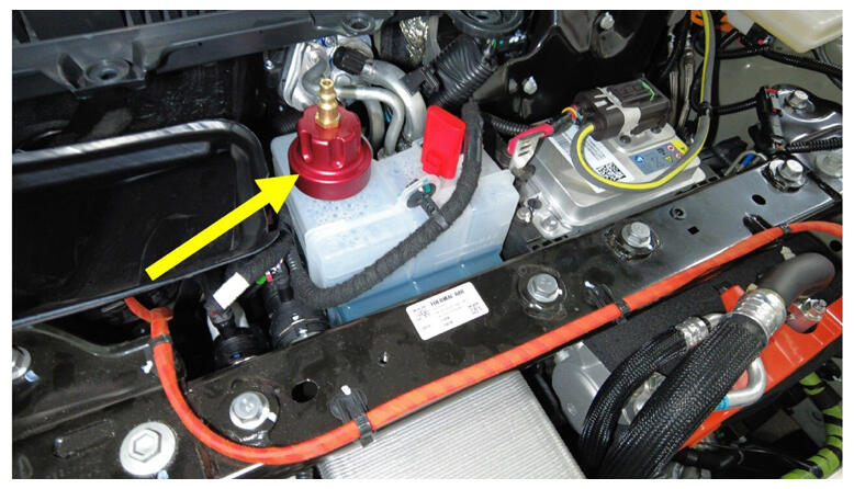 Courtesy of TESLA, INC. Courtesy of TESLA, INC.
|
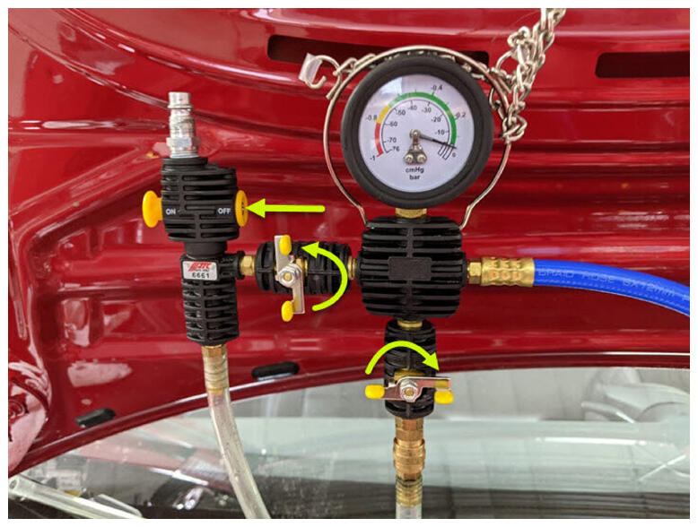
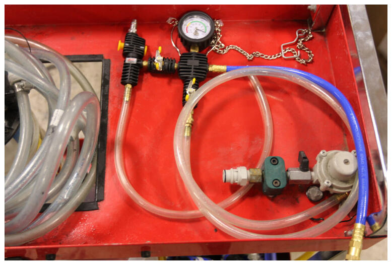
- Setup vacuum refill tool.
NOTE:
Verify all valves on refill tool are in the closed position, See image for clarity.
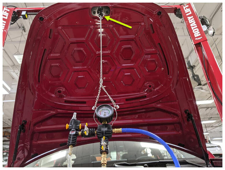 Courtesy of TESLA, INC. Courtesy of TESLA, INC.
|
 Courtesy of TESLA, INC. Courtesy of TESLA, INC.
|
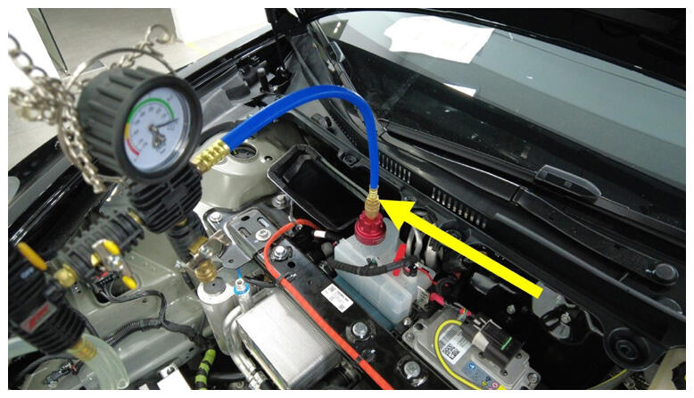
- Install vacuum refill hose into refill cap on coolant bottle.
NOTE:
Perform push-pull-push test to verify hose is fully engaged.
 Courtesy of TESLA, INC. Courtesy of TESLA, INC.
|
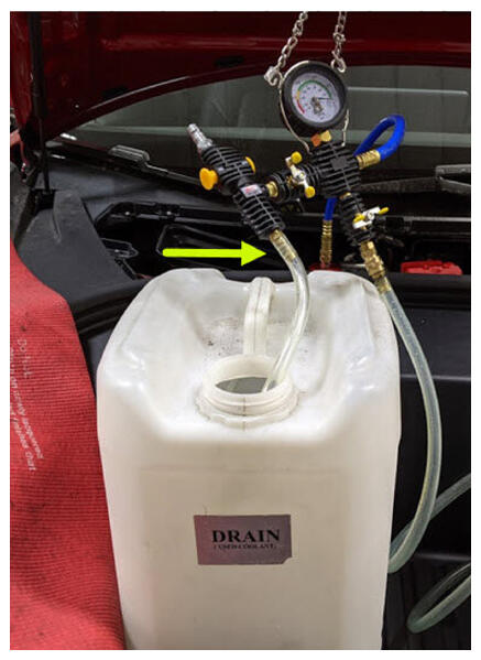
- Position overflow hose into empty container.
 Courtesy of TESLA, INC. Courtesy of TESLA, INC.
|
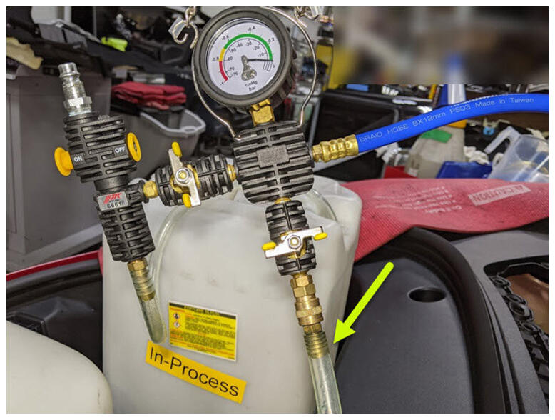
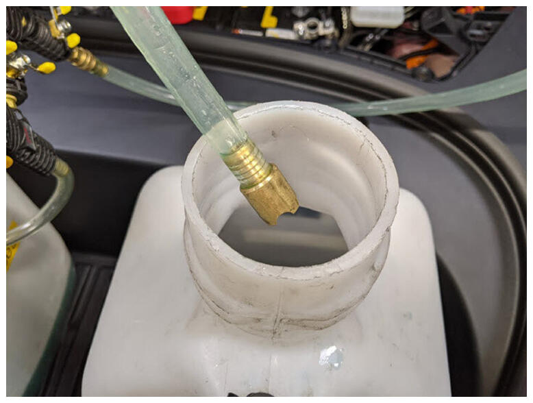
- Place refill hose inside filled coolant container.
NOTE:
Make sure hose end is fully submerged into coolant.
 Courtesy of TESLA, INC. Courtesy of TESLA, INC.
|
 Courtesy of TESLA, INC. Courtesy of TESLA, INC.
|
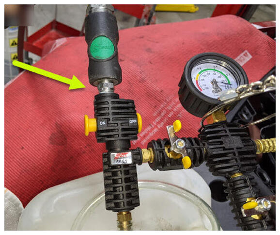
- Connect shop air supply to coolant refill tool.
NOTE:
If not already done, Verify refill valve is set to off.
 Courtesy of TESLA, INC. Courtesy of TESLA, INC.
|
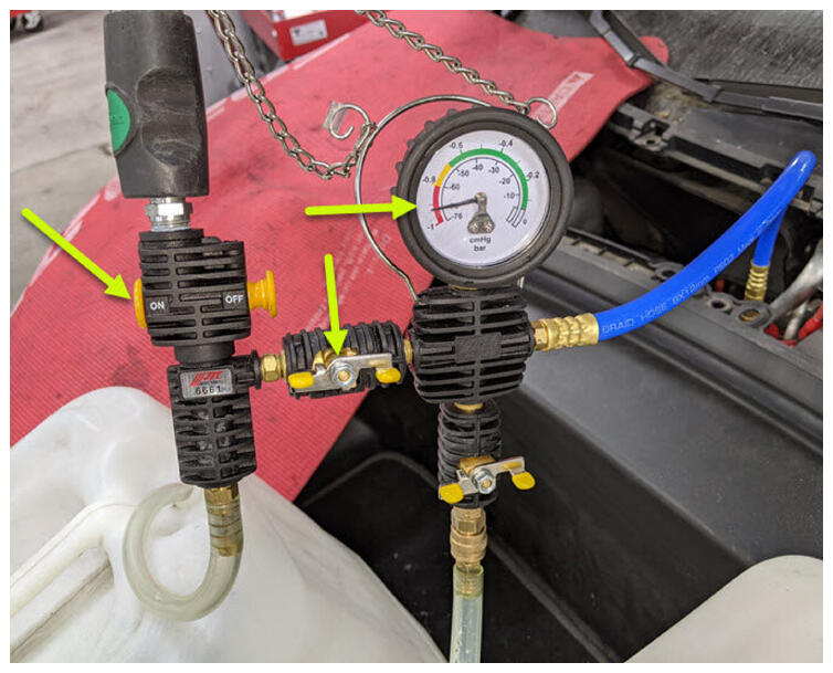
- Open air inlet valve to draw a vacuum, Once gauge stabilizes, Fully close valve.
NOTE:
Gauge stabilizes roughly (60-70 cmHg), Vacuum should not drop after the valves are closed.
 Courtesy of TESLA, INC. Courtesy of TESLA, INC.
|
 Courtesy of TESLA, INC. Courtesy of TESLA, INC.
|
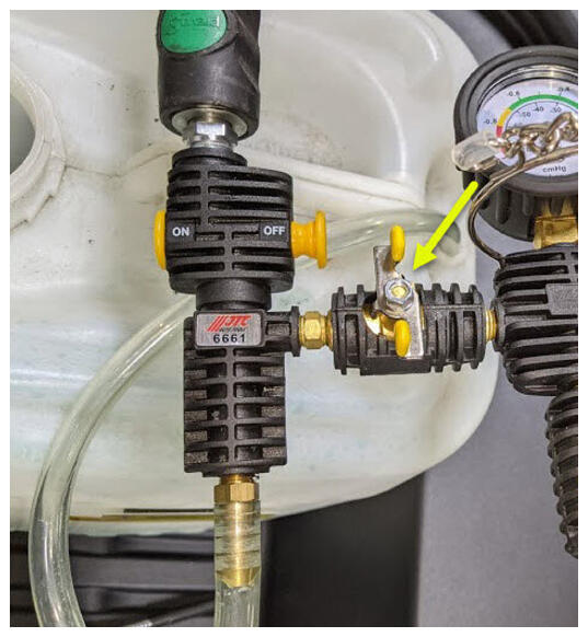
- Slowly open coolant refill valve to allow coolant to be drawn into coolant refill hose, Close valve when hose is full of coolant.
- Monitor gauge for 30 seconds to verify a vacuum is maintained in cooling system.
- Reopen the air inlet valve for 3 minutes to continue evacuating cooling system, then close valve.
- Slowly open refill valve to allow coolant to be drawn into system.
NOTE:
Make sure hose end of refill hose is fully submerged during entire process.
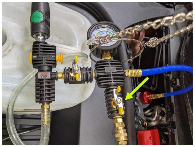 Courtesy of TESLA, INC. Courtesy of TESLA, INC.
|
- Once gauge reads zero, close refill valve.
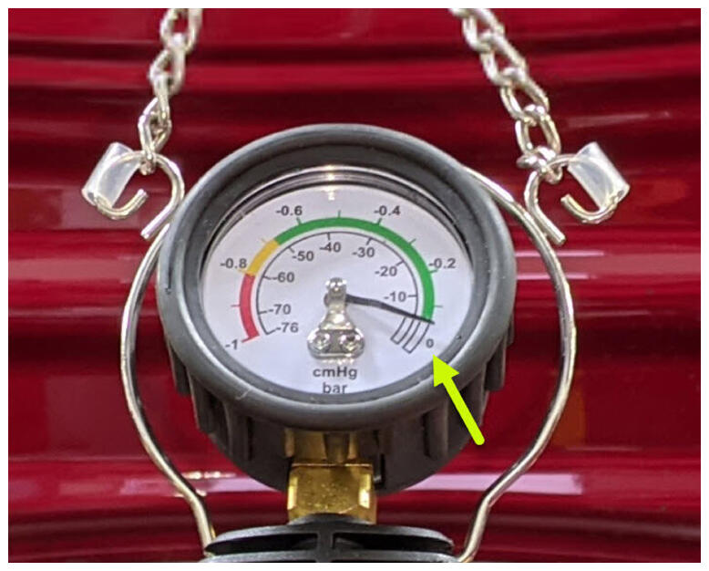 Courtesy of TESLA, INC. Courtesy of TESLA, INC.
|
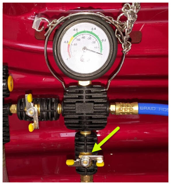 Courtesy of TESLA, INC. Courtesy of TESLA, INC.
|
- Disconnect shop air supply from coolant refill tool.
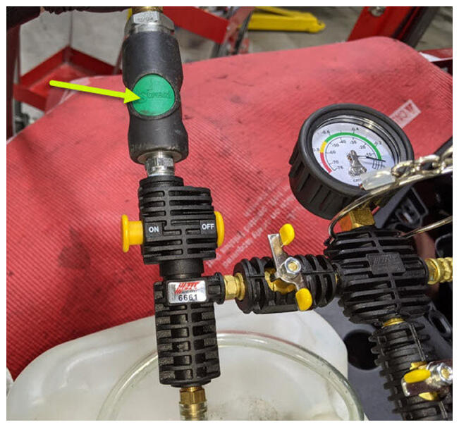 Courtesy of TESLA, INC. Courtesy of TESLA, INC.
|
- Remove coolant refill hose from coolant container.
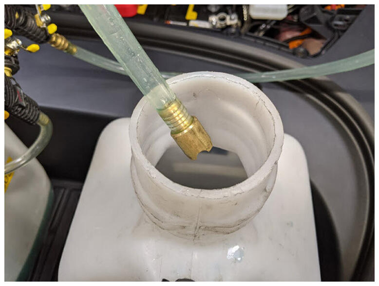 Courtesy of TESLA, INC. Courtesy of TESLA, INC.
|
- Remove coolant overflow hose from coolant container.
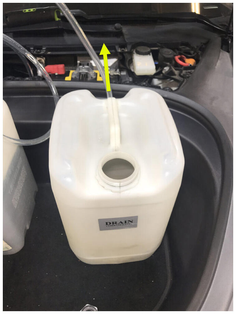 Courtesy of TESLA, INC. Courtesy of TESLA, INC.
|
- Remove vacuum refill hose from refill cap on coolant bottle.
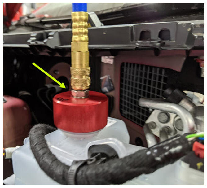 Courtesy of TESLA, INC. Courtesy of TESLA, INC.
|
- Remove coolant refill tool from vehicle.
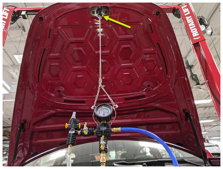 Courtesy of TESLA, INC. Courtesy of TESLA, INC.
|
 Courtesy of TESLA, INC. Courtesy of TESLA, INC.
|
- Remove both coolant containers from inside underhood area.
 Courtesy of TESLA, INC. Courtesy of TESLA, INC.
|
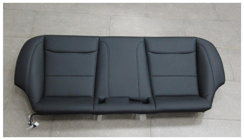
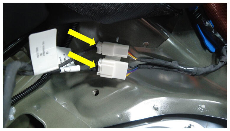
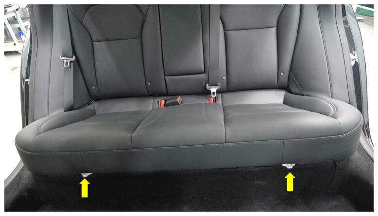
- Connect 2nd row seat harness and secure cushion.
NOTE:
2x clips, 2x connectors, Insert buckles through holes, Slide rear inward then align front clips, Perform push-pull-push test.
 Courtesy of TESLA, INC. Courtesy of TESLA, INC.
|
 Courtesy of TESLA, INC. Courtesy of TESLA, INC.
|
 Courtesy of TESLA, INC. Courtesy of TESLA, INC.
|
- Connect First Responder Loop and LV battery.
NOTE:
2x connectors, Secure FRL first, Seat LV battery connection and push black connector lock inwards to secure, Engage green locking tab when fully seated.
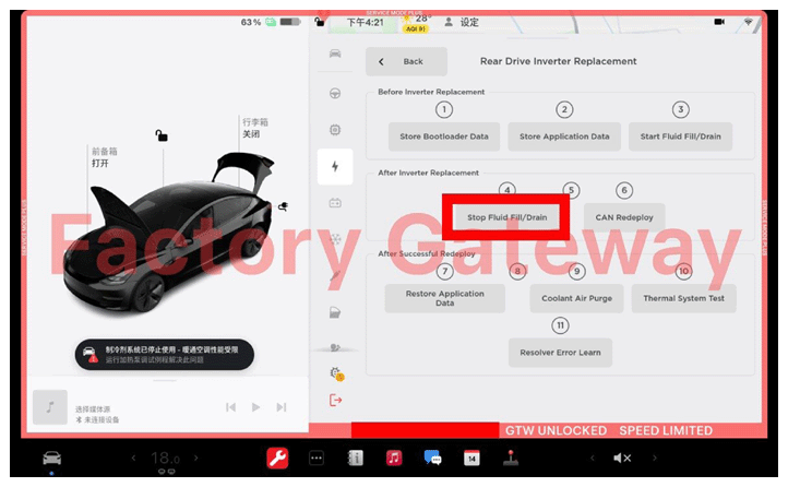
- Select "Stop Fluid Fill/Drain" through UI.
 Courtesy of TESLA, INC. Courtesy of TESLA, INC.
|
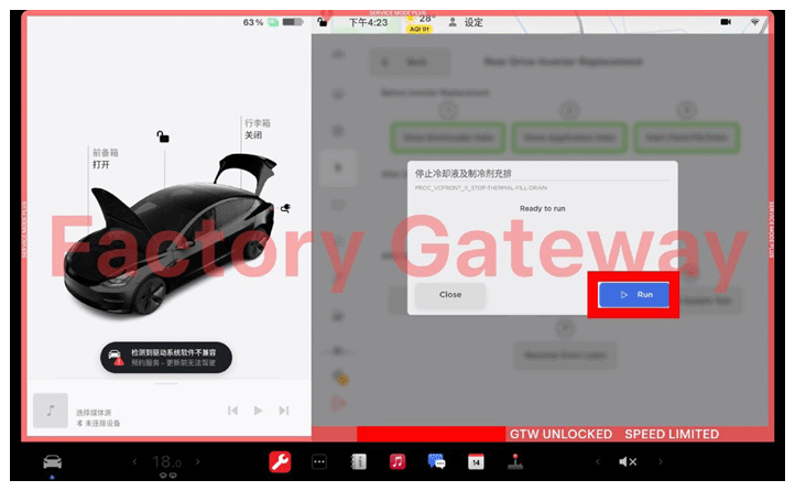
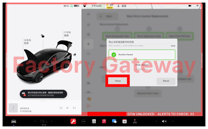
- Select "Run" through UI to Stop Fluid Fill/Drain.
NOTE:
Allow routine to complete, ensure routine is successful, then select "close" through UI.
 Courtesy of TESLA, INC. Courtesy of TESLA, INC.
|
 Courtesy of TESLA, INC. Courtesy of TESLA, INC.
|
- Select "Restore Bootloader Data" through UI.
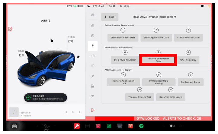 Courtesy of TESLA, INC. Courtesy of TESLA, INC.
|
- Select "Run" through UI to Restore Bootloader Data.
NOTE:
Allow routine to complete, ensure routine is successful, then select "close" through UI.
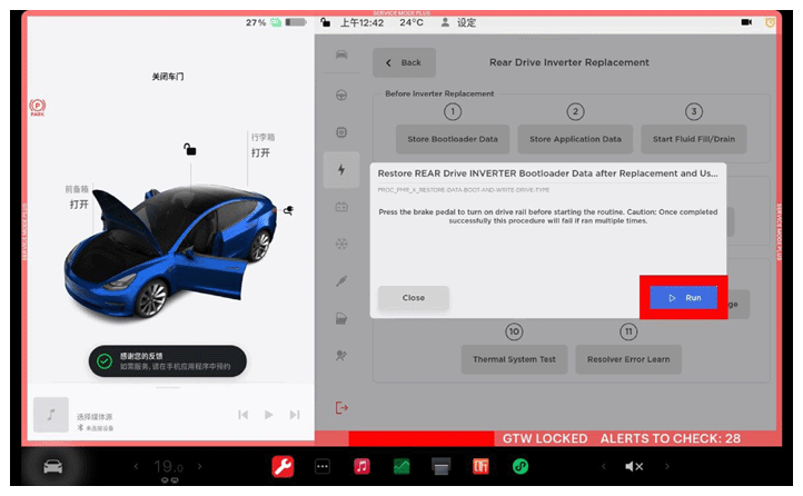 Courtesy of TESLA, INC. Courtesy of TESLA, INC.
|
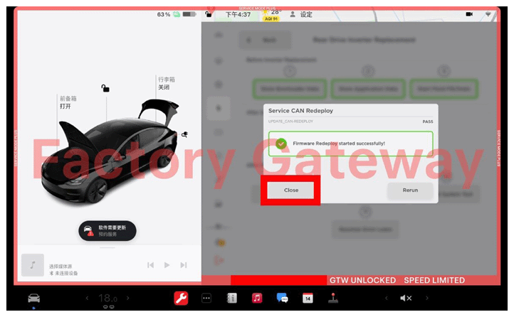
- Select "CAN Redeploy" through UI.
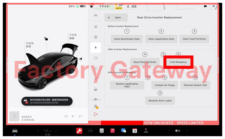 Courtesy of TESLA, INC. Courtesy of TESLA, INC.
|
- Select "Run" through UI to run CAN Redeploy.
NOTE:
Allow routine to complete, ensure routine is successful, then select "close" through UI.
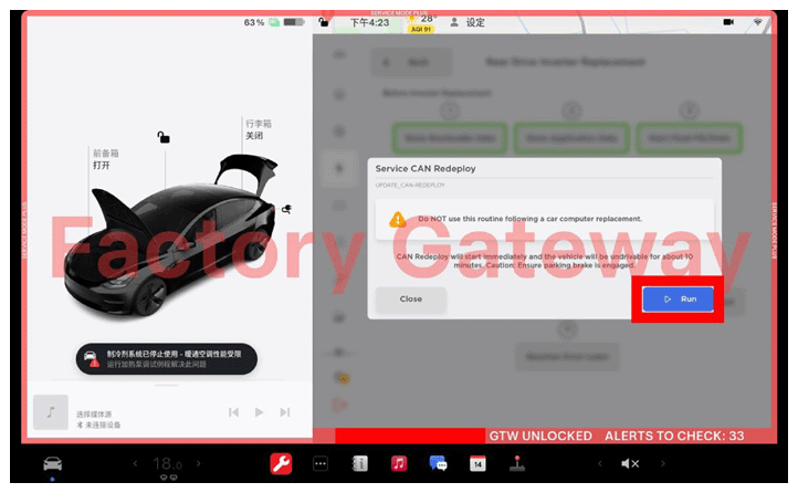 Courtesy of TESLA, INC. Courtesy of TESLA, INC.
|
 Courtesy of TESLA, INC. Courtesy of TESLA, INC.
|
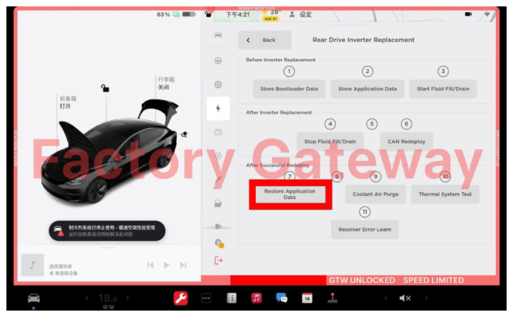
- Select "Restore Application Data" through UI.
 Courtesy of TESLA, INC. Courtesy of TESLA, INC.
|
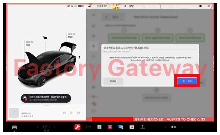
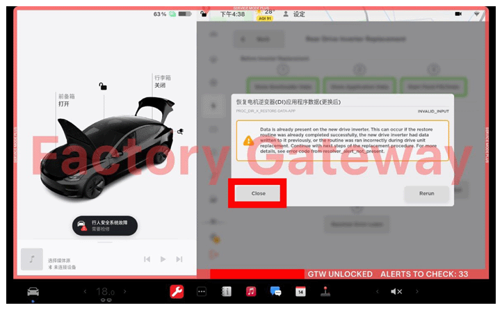
- Select "Run" through UI to Restore Application Data.
NOTE:
Allow routine to complete, ensure routine is successful, then select "close" through UI.
 Courtesy of TESLA, INC. Courtesy of TESLA, INC.
|
 Courtesy of TESLA, INC. Courtesy of TESLA, INC.
|
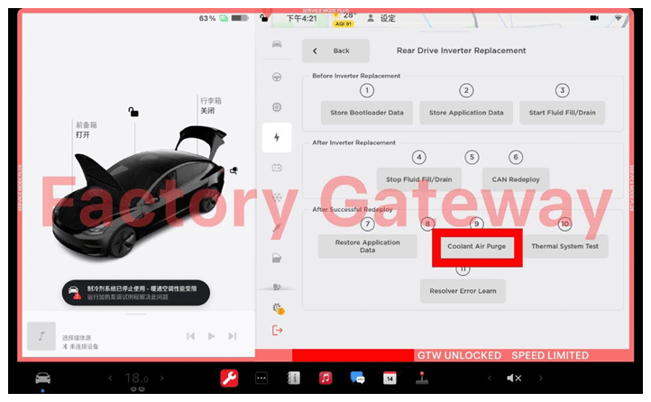
- Select "Coolant Air Purge" through UI.
 Courtesy of TESLA, INC. Courtesy of TESLA, INC.
|
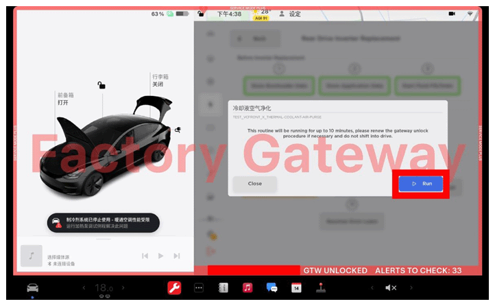
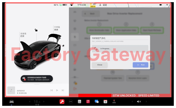
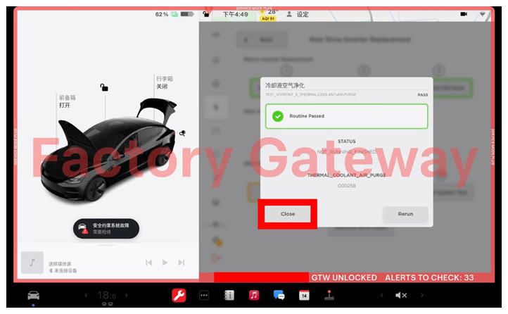
- Select "Run" through UI to run Coolant Air Purge.
NOTE:
Allow routine to complete, ensure routine is successful, then select "close" through UI.
 Courtesy of TESLA, INC. Courtesy of TESLA, INC.
|
 Courtesy of TESLA, INC. Courtesy of TESLA, INC.
|
 Courtesy of TESLA, INC. Courtesy of TESLA, INC.
|
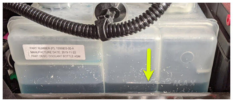
- Inspect coolant level and top off as necessary.
NOTE:
Ensure that fluid level is at Max line.
 Courtesy of TESLA, INC. Courtesy of TESLA, INC.
|
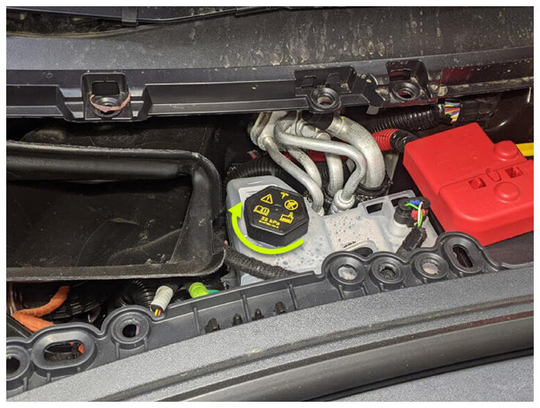
- Install coolant bottle cap.
 Courtesy of TESLA, INC. Courtesy of TESLA, INC.
|
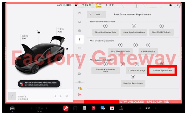
- Select "Thermal system Test" through UI.
 Courtesy of TESLA, INC. Courtesy of TESLA, INC.
|
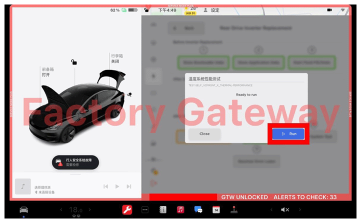
- Select "Run" through UI to run Thermal system Test.
NOTE:
Allow routine to complete, ensure routine is successful, then select "close" through UI.
 Courtesy of TESLA, INC. Courtesy of TESLA, INC.
|
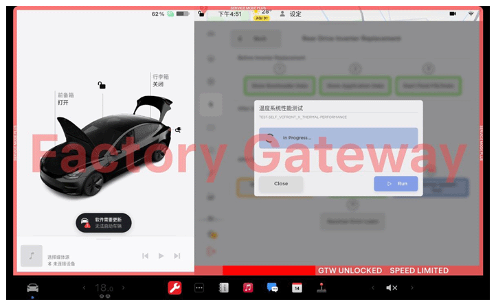 Courtesy of TESLA, INC. Courtesy of TESLA, INC.
|
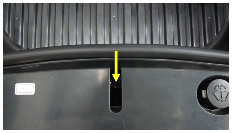
- Manually engage the hood latch.
NOTE:
Manually engage hood latch for resolver error learn.
 Courtesy of TESLA, INC. Courtesy of TESLA, INC.
|
- Place stanchions around vehicle and set up a safety perimeter before performing resolver error learn.
NOTE:
Use safety stanchions to section off vehicle before driving vehicle on a lift.
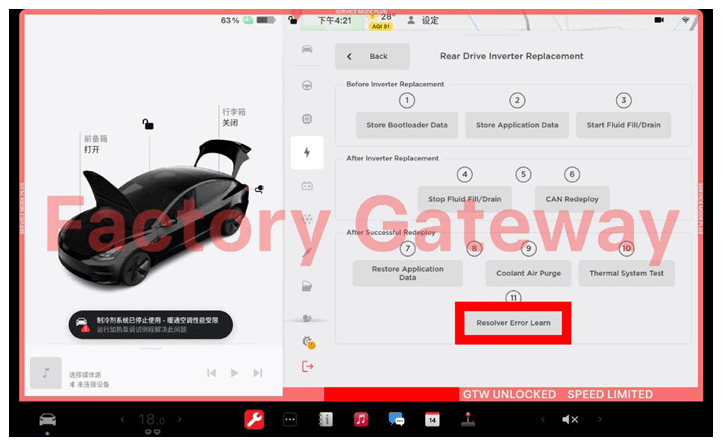
- Press brake pedal to turn on drive rails.
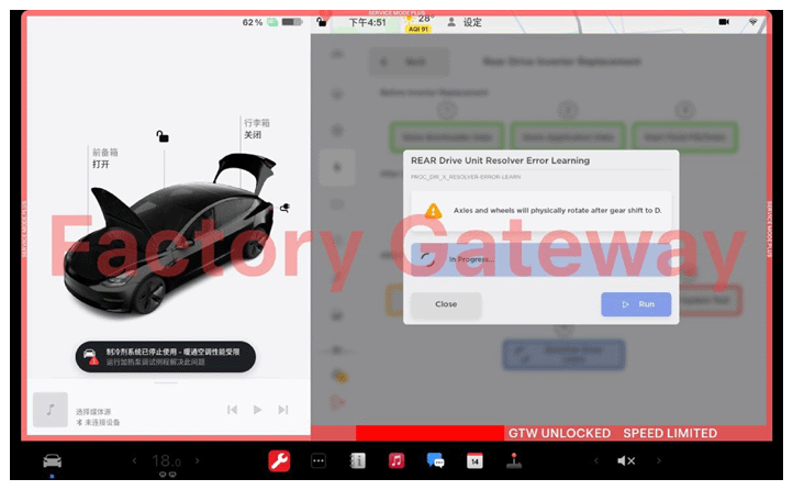
- Select "Resolver Error Learn" through UI.
 Courtesy of TESLA, INC. Courtesy of TESLA, INC.
|
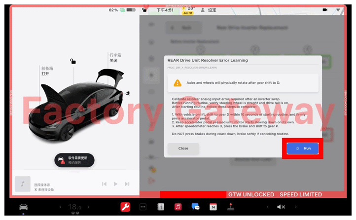
- Select "Run" through UI to run Resolver Error Learn.
NOTE:
Allow routine to complete, ensure routine is successful, then select "close" through UI.
 Courtesy of TESLA, INC. Courtesy of TESLA, INC.
|
 Courtesy of TESLA, INC. Courtesy of TESLA, INC.
|
- Disable Service Mode. See SERVICE MODE
.
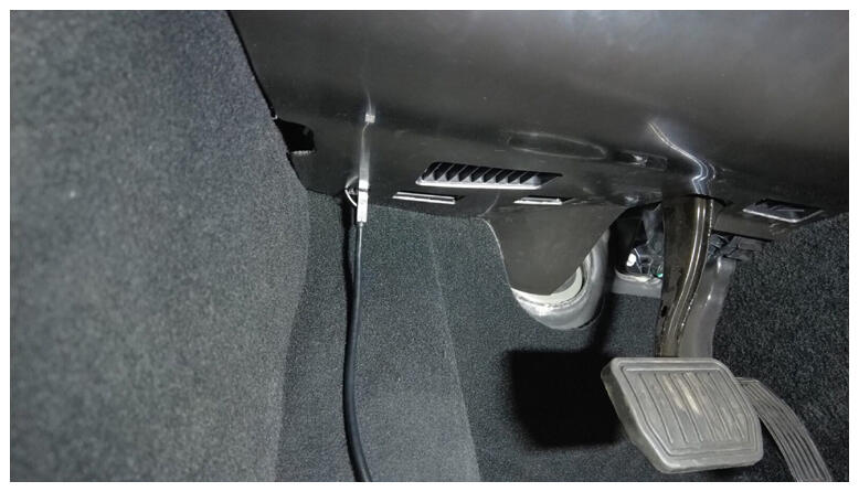
- Remove diagnostic cable from port to disconnect Toolbox 3.0 from vehicle.
 Courtesy of TESLA, INC. Courtesy of TESLA, INC.
|
- Install both rear wheels. See WHEEL ASSEMBLY - REMOVE AND INSTALL
.
- Remove safety stanchions from around vehicle after resolver learn is completed.
NOTE:
Remove all stanchions after vehicle is finished with the resolver error learn.
- Install the rear underhood apron. See UNDERHOOD TRIM - REAR APRON ASSEMBLY - REMOVE AND REPLACE
.
- Move the LH and RH front seats to original position.
- Raise all windows and close all doors.
- Remove the lift arms from below the vehicle.
- Refer to the Alignment Requirement tables to determine whether an EPAS alignment check (EC) or four wheel alignment check (AC) is necessary. If performed, add the alignment check/adjust as a separate activity. See ALIGNMENT REQUIREMENT - SUSPENSION
.