- Raise and support the vehicle on a 2 post lift. See Raise Vehicle - 2 Post Lift .
- Connect a laptop with Toolbox to the vehicle. See Toolbox 3 (Connect and Disconnect)
.
- In Toolbox, click Actions/Autodiag
, and then search for 'Thermal.'
- Click Start Thermal Fluid Fill/Drain (Coolant only)
, and then click Run
. Allow the routine to complete.
- Remove the laptop from the vehicle.
NOTE:
Toolbox will be resumed later.
- Set the steering yoke straight ahead.
- Lock the steering yoke into position.
NOTE:
Protect the seat from damage.
- Remove the rear underhood apron. See Underhood Apron - Rear (Remove and Replace)
.
- Power off vehicle from center display
NOTE:
Via Controls > Safety & Security > Power Off
- Disconnect LV power. See LV Power (Disconnect and Connect)
.
- Remove the mid aero shield. See Panel - Aero Shield - Mid (Remove and Replace)
.
- Perform the vehicle electrical isolation procedure. See Vehicle Electrical Isolation Procedure
.
- Remove the LH and RH front wheels. See Wheel (Remove and Install)
.
- Remove the LH and RH rocker panel scuff plates. See Scuff Plate - Rocker Panel - LH (Remove and Replace)
.
- Remove the LH and RH rocker panel moldings. See Molding - Rocker Panel - LH (Remove and Replace)
.
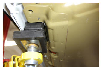
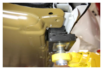
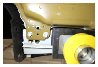
- Raise and support vehicle for HV battery removal
NOTE:
Set air suspension to "Jack Mode" if equipped, Line up all lift pads at vehicle lifting points, Ensure lift pads will be positioned properly. If not done correctly HV pack will physically contact the lift pad during removal
 Courtesy of TESLA, INC. Courtesy of TESLA, INC.
|
 Courtesy of TESLA, INC. Courtesy of TESLA, INC.
|
 Courtesy of TESLA, INC. Courtesy of TESLA, INC.
|
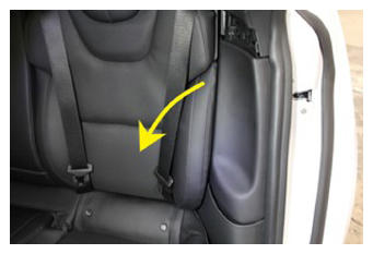
- Remove LH side bolster trim
NOTE:
1x clip, 1x tab, Start by releasing upper portion
 Courtesy of TESLA, INC. Courtesy of TESLA, INC.
|
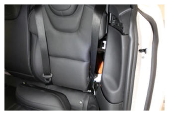 Courtesy of TESLA, INC. Courtesy of TESLA, INC.
|
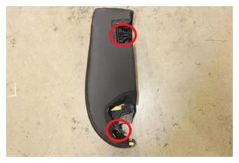 Courtesy of TESLA, INC. Courtesy of TESLA, INC.
|
- Remove RH side bolster trim
NOTE:
1x clip, 1x tab, Start by releasing upper portion
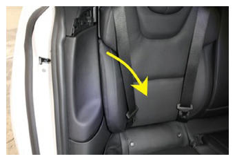 Courtesy of TESLA, INC. Courtesy of TESLA, INC.
|
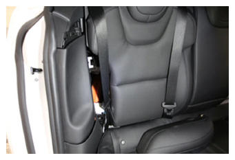 Courtesy of TESLA, INC. Courtesy of TESLA, INC.
|
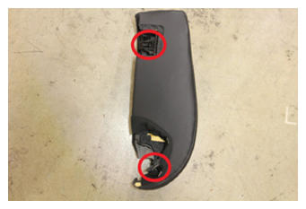 Courtesy of TESLA, INC. Courtesy of TESLA, INC.
|
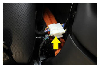
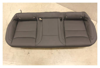
- Remove 2nd row seat cushion assembly
NOTE:
2x clips, 2x connectors, Disengage locking clips and lift up on seat cushion, Release connections, If second row seats are folded down, move aside for time being
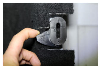 Courtesy of TESLA, INC. Courtesy of TESLA, INC.
|
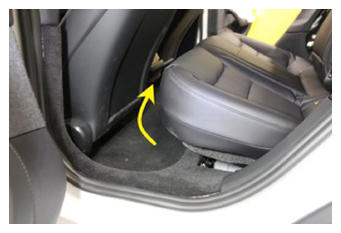 Courtesy of TESLA, INC. Courtesy of TESLA, INC.
|
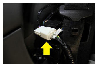 Courtesy of TESLA, INC. Courtesy of TESLA, INC.
|
 Courtesy of TESLA, INC. Courtesy of TESLA, INC.
|
 Courtesy of TESLA, INC. Courtesy of TESLA, INC.
|
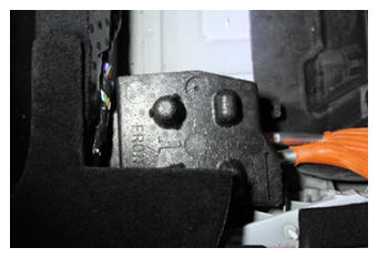
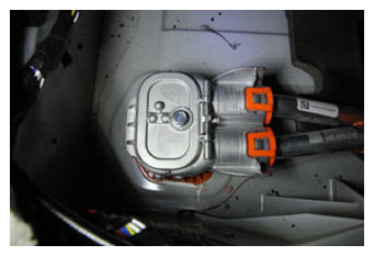
- Remove busbar header foam block
 Courtesy of TESLA, INC. Courtesy of TESLA, INC.
|
 Courtesy of TESLA, INC. Courtesy of TESLA, INC.
|
- Remove fastener securing busbar cover access door
NOTE:
1x bolt, 10 mm, 9 N.m
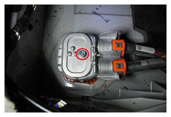 Courtesy of TESLA, INC. Courtesy of TESLA, INC.
|
- Remove bolts securing busbar to HV header and release busbar
NOTE:
2x bolts, 10 mm, 9 N.m
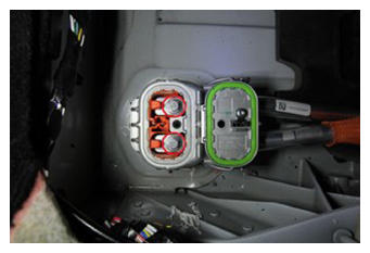 Courtesy of TESLA, INC. Courtesy of TESLA, INC.
|
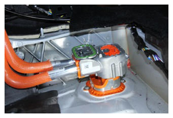 Courtesy of TESLA, INC. Courtesy of TESLA, INC.
|
- Raise vehicle fully and lower lift onto locks
NOTE:
Set vehicle to comfortable working height, Make sure there's an audible click of the locks on both sides before lowering, otherwise vehicle may tilt to the side
- Remove clips securing front aero shield
NOTE:
5x push clips
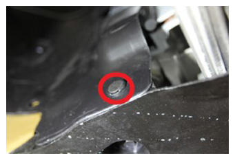 Courtesy of TESLA, INC. Courtesy of TESLA, INC.
|
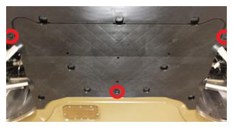 Courtesy of TESLA, INC. Courtesy of TESLA, INC.
|
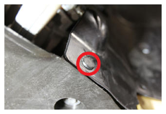 Courtesy of TESLA, INC. Courtesy of TESLA, INC.
|
- Remove bolts securing front aero shield and remove from vehicle
NOTE:
9x bolts, 10 mm, 6 N.m
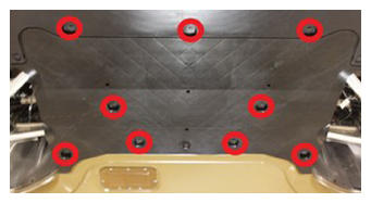 Courtesy of TESLA, INC. Courtesy of TESLA, INC.
|
- Release clips securing wheel house liner to skid plate
NOTE:
4x clips
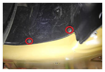 Courtesy of TESLA, INC. Courtesy of TESLA, INC.
|
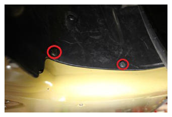 Courtesy of TESLA, INC. Courtesy of TESLA, INC.
|
- Remove bolts securing front skid plate to body sill
NOTE:
2x bolts, 15 mm, 30 N.m
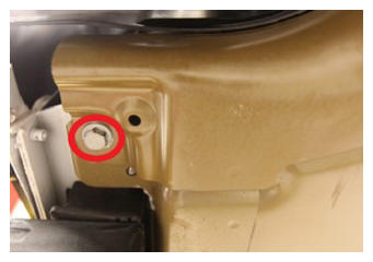 Courtesy of TESLA, INC. Courtesy of TESLA, INC.
|
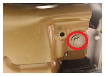 Courtesy of TESLA, INC. Courtesy of TESLA, INC.
|
- Remove bolts securing front skid plate to body casting
NOTE:
2x bolts, 15 mm, 60 N.m
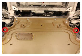 Courtesy of TESLA, INC. Courtesy of TESLA, INC.
|
- Remove bolts securing front skid plate to front subframe and remove skidplate
NOTE:
4x bolts, 15 mm, 70 N.m
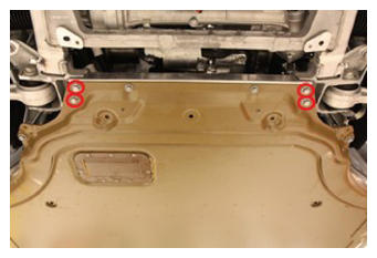 Courtesy of TESLA, INC. Courtesy of TESLA, INC.
|
- Remove clips securing LH wheelhouse liner to valance and front fascia
NOTE:
3x push clips
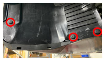 Courtesy of TESLA, INC. Courtesy of TESLA, INC.
|
- Remove clips securing RH wheelhouse liner to valance and front fascia
NOTE:
3x push clips
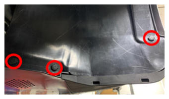 Courtesy of TESLA, INC. Courtesy of TESLA, INC.
|
- Disconnect and release pedestrian warning speaker connector
NOTE:
1x connector, Do not push down on red tab, Pull red tab to disengage lock, Pull again to release connector, 1x edge clip, Located on RH ride of front fascia valance
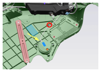 Courtesy of TESLA, INC. Courtesy of TESLA, INC.
|
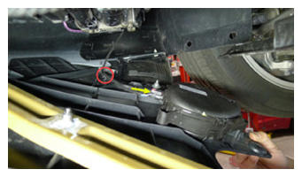 Courtesy of TESLA, INC. Courtesy of TESLA, INC.
|
- Remove clips that secure valance to front fascia assembly
NOTE:
8x push clips
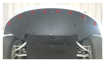 Courtesy of TESLA, INC. Courtesy of TESLA, INC.
|
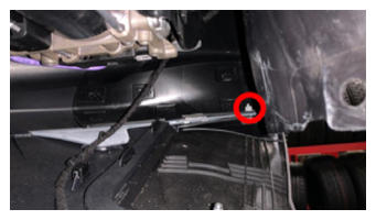
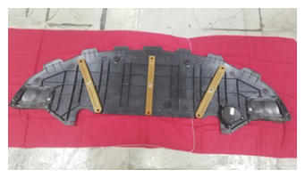
- Remove valance from front fascia assembly
NOTE:
2x nuts, 10 mm, 3 N.m
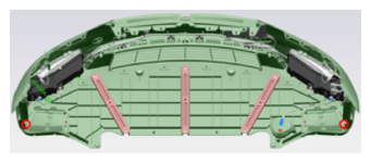 Courtesy of TESLA, INC. Courtesy of TESLA, INC.
|
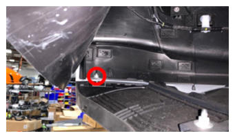 Courtesy of TESLA, INC. Courtesy of TESLA, INC.
|
 Courtesy of TESLA, INC. Courtesy of TESLA, INC.
|
 Courtesy of TESLA, INC. Courtesy of TESLA, INC.
|
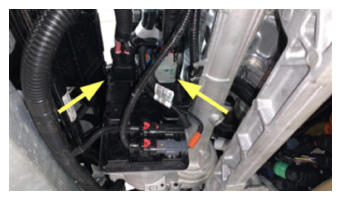
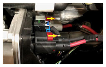
- Disconnect the steering gear assembly connectors
NOTE:
2x connectors, Two stage connectors, Slide red locking tab to unlock, then depress the connector release to disconnect
 Courtesy of TESLA, INC. Courtesy of TESLA, INC.
|
 Courtesy of TESLA, INC. Courtesy of TESLA, INC.
|
- Disconnect CAN connectors from EPAS
NOTE:
2x connectors
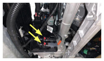 Courtesy of TESLA, INC. Courtesy of TESLA, INC.
|
- Release frunk harness from subframe
NOTE:
2x clips, Tuck harness upwards, away from subframe
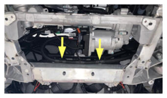 Courtesy of TESLA, INC. Courtesy of TESLA, INC.
|
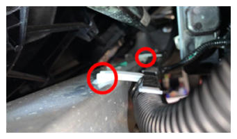 Courtesy of TESLA, INC. Courtesy of TESLA, INC.
|
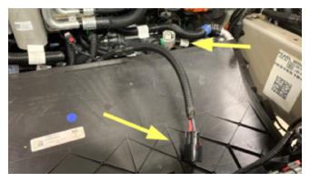 Courtesy of TESLA, INC. Courtesy of TESLA, INC.
|
- Remove bolt securing the steering gear assembly to electric steering column
NOTE:
1x bolt, 13 mm, 30 N.m
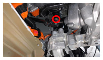 Courtesy of TESLA, INC. Courtesy of TESLA, INC.
|
- Slide the steering column upward to remove it from the steering gear assembly
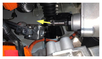 Courtesy of TESLA, INC. Courtesy of TESLA, INC.
|
- Lower vehicle partially and set lift onto locks
NOTE:
Raise lift off locks, then hold lock release lever to keep locks free while vehicle is lowered, Set vehicle to comfortable working height
- Remove LH front wheel
NOTE:
5x nuts, 21 mm, 175 N.m
- Release LH ANC sensor and damper bracket from air spring module
NOTE:
1x bolt, 10 mm, 6 N.m, Route around links and hang, Take note of how the harness is routed for installation
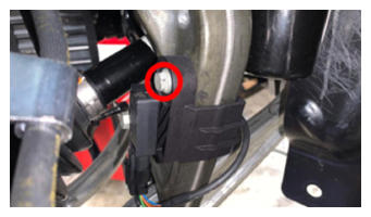 Courtesy of TESLA, INC. Courtesy of TESLA, INC.
|
- Remove nut securing front stabar link to LH front stabar and move aside
NOTE:
1x nyloc nut, 15 mm, 70 N.m, Counter hold ball joint with T40, Discard after removal, May need to move the stabilizer bar up/down to get the correct angle needed to remove end link
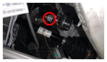 Courtesy of TESLA, INC. Courtesy of TESLA, INC.
|
- Remove nut and bolt securing LH front air spring module to front lower aft link assembly
NOTE:
1x bolt, 21 mm, 1x nut, 21 mm, 140 N.m
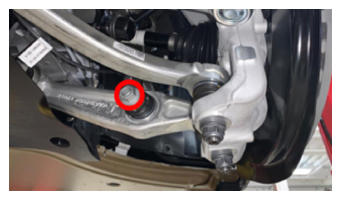 Courtesy of TESLA, INC. Courtesy of TESLA, INC.
|
- Remove nut and release LH aft link from knuckle assembly
NOTE:
1x nut, 22 mm, 180 N.m, Nordlok washer, Counter hold stud with T45 socket and use wrench to loosen nut, Discard after removal
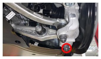 Courtesy of TESLA, INC. Courtesy of TESLA, INC.
|
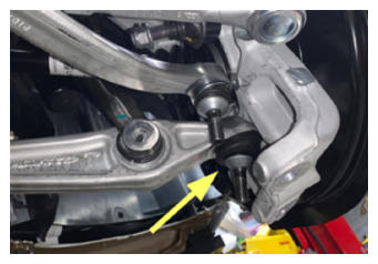 Courtesy of TESLA, INC. Courtesy of TESLA, INC.
|
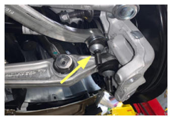
- Remove nut and release LH fore link from knuckle assembly
NOTE:
1x nut, 22 mm, 180 N.m, Nordlok washer, Counter hold stud with T45 socket and use wrench to loosen nut, Discard after removal
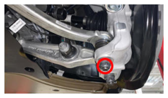 Courtesy of TESLA, INC. Courtesy of TESLA, INC.
|
 Courtesy of TESLA, INC. Courtesy of TESLA, INC.
|
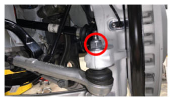
- Remove nut and release LH tie rod from knuckle assembly
NOTE:
1x nyloc nut, 21 mm, 102 N.m, Discard after removal
 Courtesy of TESLA, INC. Courtesy of TESLA, INC.
|
- Remove RH front wheel
NOTE:
5x nuts, 21 mm, 175 N.m
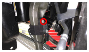
- Release RH ANC sensor and damper bracket from air spring module
NOTE:
1x bolt, 10 mm, 6 N.m, Route around links and hang, Take note of how the harness is routed for installation
 Courtesy of TESLA, INC. Courtesy of TESLA, INC.
|
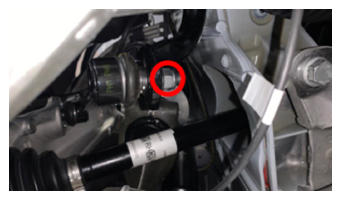
- Remove nut securing front stabar link to RH front stabar and move aside
NOTE:
1x nyloc nut, 15 mm, 70 N.m, Counter hold ball joint with T40, Discard after removal, May need to move the stabilizer bar up/down to get the correct angle needed to remove end link
 Courtesy of TESLA, INC. Courtesy of TESLA, INC.
|
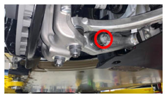
- Remove nut and bolt securing RH front air spring module to front lower aft link assembly
NOTE:
1x bolt, 21 mm, 1x nut, 21 mm, 140 N.m
 Courtesy of TESLA, INC. Courtesy of TESLA, INC.
|
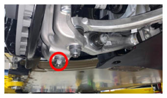
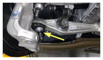
- Remove nut and release RH aft link from knuckle assembly
NOTE:
1x nut, 21 mm, 195 N.m, Nordlok washer, Counter hold stud with T45 socket and use wrench to loosen nut, Discard after removal
 Courtesy of TESLA, INC. Courtesy of TESLA, INC.
|
 Courtesy of TESLA, INC. Courtesy of TESLA, INC.
|
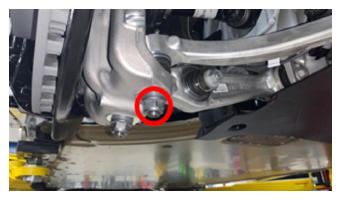
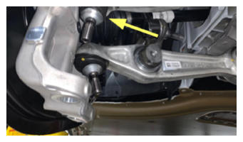
- Remove nut and release RH fore link from knuckle assembly
NOTE:
1x nut, 21 mm, 195 N.m, Nordlok washer, Counter hold stud with T45 socket and use wrench to loosen nut, Discard after removal
 Courtesy of TESLA, INC. Courtesy of TESLA, INC.
|
 Courtesy of TESLA, INC. Courtesy of TESLA, INC.
|
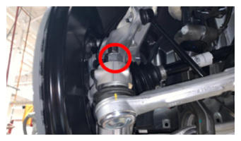
- Remove nut securing the RH tie rod end to the knuckle
NOTE:
1x nyloc nut, 21 mm, 102 N.m, Discard after removal
 Courtesy of TESLA, INC. Courtesy of TESLA, INC.
|
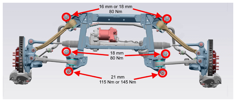
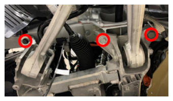
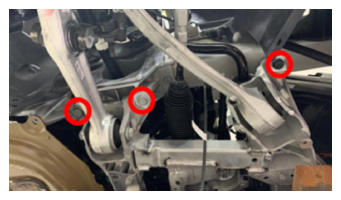
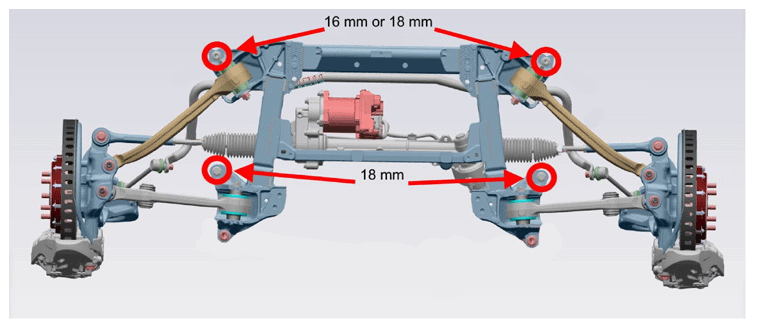
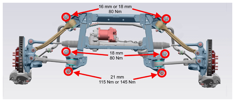
- Break loose the front subframe bolts, but do not remove the bolts at this time.
NOTE:
Torque specifications:
Depending on the vehicle manufacture date, the bolts might be as follows:
- Front-most bolts (16 mm or 18 mm):
- M12 1.75 x 75 bolt (1063242-00-B) and M12 x 24 x 2.5 washer (1103852-00-A): 80 N.m
- M12 1.75 x 115 bolt (1608611-00-C): 80 N.m
- Middle bolts (18 mm): 80 N.m
- Rear-most bolts (21 mm):
- M14 2.0 x 58 bolt (1133941-00-C): 115 N.m
- M14 2.0 x 67 bolt (1638540-00-A): 145 N.m
 Courtesy of TESLA, INC.
 Courtesy of TESLA, INC. Courtesy of TESLA, INC.
|
 Courtesy of TESLA, INC. Courtesy of TESLA, INC.
|
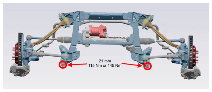
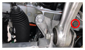
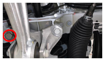
- Remove the rear-most subframe bolts with a battery-powered drill.
NOTE:
21 mm: 115 N.m or 145 N.m
 Courtesy of TESLA, INC.
 Courtesy of TESLA, INC. Courtesy of TESLA, INC.
|
 Courtesy of TESLA, INC. Courtesy of TESLA, INC.
|
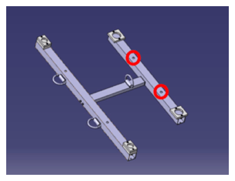
- Remove forward-most subframe fixture hardware
NOTE:
Bolts will clash with subframe if not removed, Return bolts to fixture when finished with procedure
 Courtesy of TESLA, INC. Courtesy of TESLA, INC.
|
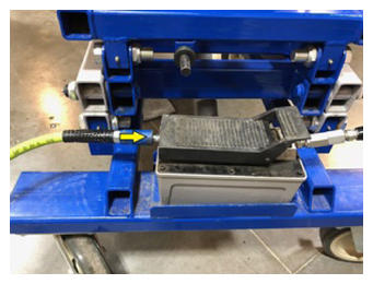
- Move the subframe lifting tool underneath the front subframe area
- Connect air supply to subframe lifting tool
 Courtesy of TESLA, INC. Courtesy of TESLA, INC.
|
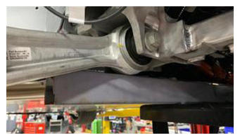
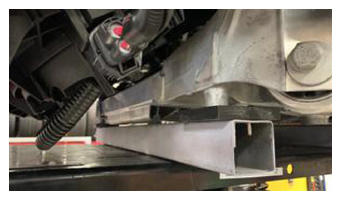
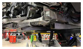
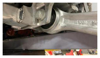
- Raise the powertrain table and subframe fixture into position
NOTE:
Recommend assistance, Lower aft links will sit on fixture
 Courtesy of TESLA, INC. Courtesy of TESLA, INC.
|
 Courtesy of TESLA, INC. Courtesy of TESLA, INC.
|
 Courtesy of TESLA, INC. Courtesy of TESLA, INC.
|
 Courtesy of TESLA, INC. Courtesy of TESLA, INC.
|
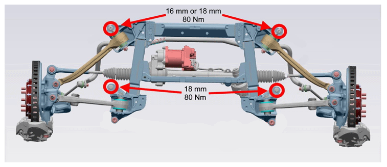
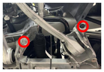
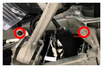
- Remove the remaining front subframe bolts with a battery-powered drill.
NOTE:
16 mm or 18 mm: 80 N.m
NOTE:
Take note of fastener positions for installation.
 Courtesy of TESLA, INC.
 Courtesy of TESLA, INC. Courtesy of TESLA, INC.
|
 Courtesy of TESLA, INC. Courtesy of TESLA, INC.
|
- Lower front subframe from vehicle
NOTE:
Recommend assistance, Knuckle assembly and strut brackets will have to be maneuvered so that the links will clear
- Disconnect air supply from subframe lifting tool
- Remove subframe lifting tool from under vehicle
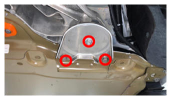
- Remove RH shear plate
NOTE:
1x nut, 15 mm, 60 N.m, 2x bolts, 10 mm, 30 N.m
 Courtesy of TESLA, INC. Courtesy of TESLA, INC.
|
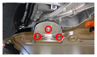
- Remove LH shear plate
NOTE:
1x nut, 15 mm, 60 N.m, 2x bolts, 10 mm, 30 N.m
 Courtesy of TESLA, INC. Courtesy of TESLA, INC.
|
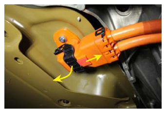
- Release RDU HV harness from HV battery
NOTE:
1x connector, Hold down red locking tab and disengage the release lever, Do not force the release lever up
 Courtesy of TESLA, INC. Courtesy of TESLA, INC.
|
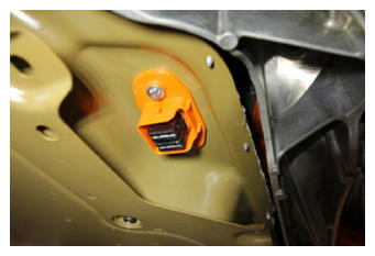 Courtesy of TESLA, INC. Courtesy of TESLA, INC.
|
- Disconnect logic connector to HV battery
NOTE:
1x connector, Pull red locking tab outwards and release connection
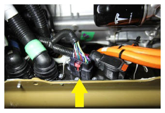 Courtesy of TESLA, INC. Courtesy of TESLA, INC.
|
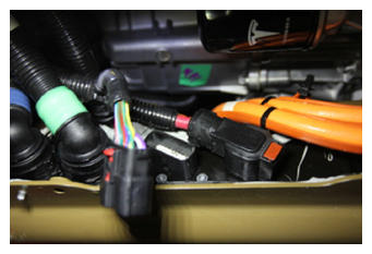 Courtesy of TESLA, INC. Courtesy of TESLA, INC.
|
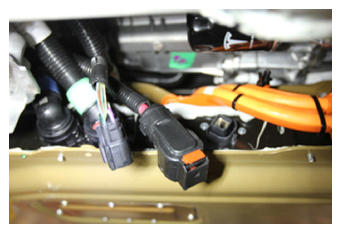
- Disconnect power connector to HV battery
NOTE:
1x connector, Pull red locking tab outwards and release connection
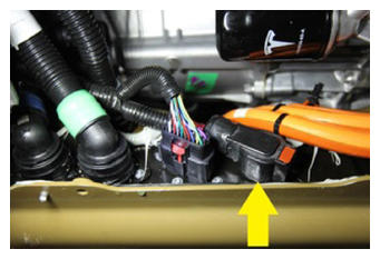 Courtesy of TESLA, INC. Courtesy of TESLA, INC.
|
 Courtesy of TESLA, INC. Courtesy of TESLA, INC.
|
- Position coolant drain container under the front of the vehicle to catch vehicle coolant
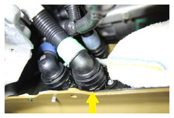
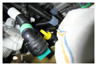
- Release 3 way valve coolant hose to HV battery
NOTE:
1x hose clip, Plug hose and battery, Use a shop rag to prevent coolant seepage into connections
 Courtesy of TESLA, INC. Courtesy of TESLA, INC.
|
 Courtesy of TESLA, INC. Courtesy of TESLA, INC.
|
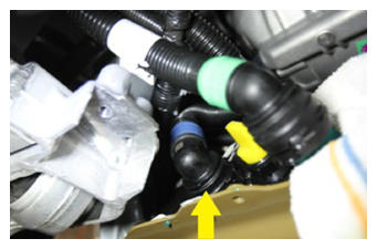
- Release battery supply coolant hose to HV battery
NOTE:
1x hose clip, Plug hose and battery
 Courtesy of TESLA, INC. Courtesy of TESLA, INC.
|
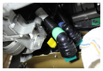 Courtesy of TESLA, INC. Courtesy of TESLA, INC.
|
- Release PCS inlet hose to HV battery
NOTE:
1x hose clip, Plug hose and battery, Remove shop rag when finished
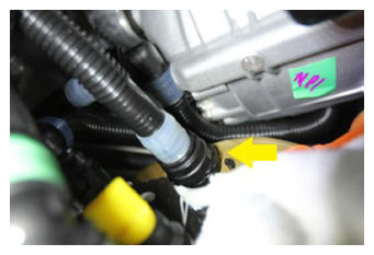 Courtesy of TESLA, INC. Courtesy of TESLA, INC.
|
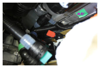 Courtesy of TESLA, INC. Courtesy of TESLA, INC.
|
- Release clips on LH front wheel house liner
NOTE:
2x clips, Move aside for access
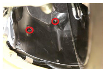 Courtesy of TESLA, INC. Courtesy of TESLA, INC.
|
- Release LH sill coolant hose clips to body
NOTE:
2x clips
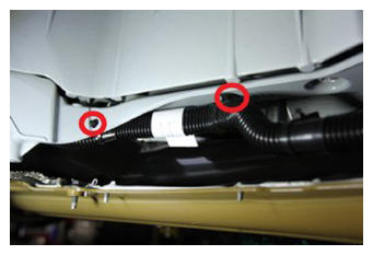 Courtesy of TESLA, INC. Courtesy of TESLA, INC.
|
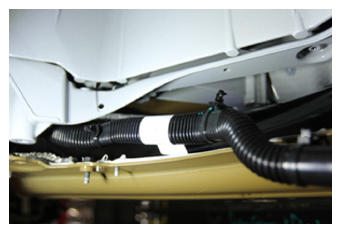 Courtesy of TESLA, INC. Courtesy of TESLA, INC.
|
- Release LH front sill coolant hose
NOTE:
1x hose clip, Plug both ends of the hoses
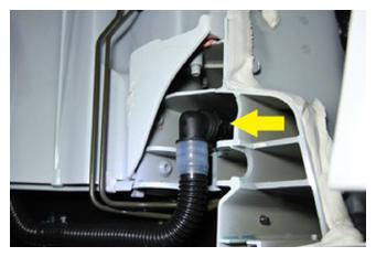 Courtesy of TESLA, INC. Courtesy of TESLA, INC.
|
- Release bolt securing ground strap to body
NOTE:
1x bolt, 10 mm, 10 N.m
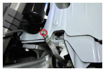 Courtesy of TESLA, INC. Courtesy of TESLA, INC.
|
- Remove coolant drain container from underneath vehicle
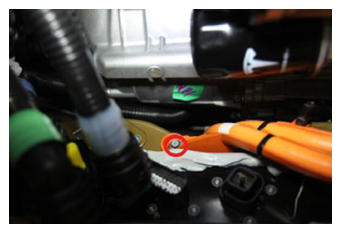
- Remove bolt securing FDU HV harness to HV battery
NOTE:
1x bolt, 8 mm, 5.5 N.m
 Courtesy of TESLA, INC. Courtesy of TESLA, INC.
|
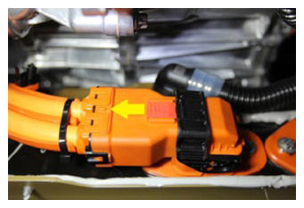
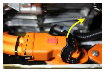
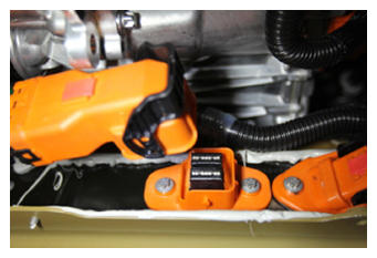
- Release FDU HV harness connection to HV battery
NOTE:
1x connector, Hold down red locking tab and disengage the release lever, Do not force the release lever up
 Courtesy of TESLA, INC. Courtesy of TESLA, INC.
|
 Courtesy of TESLA, INC. Courtesy of TESLA, INC.
|
 Courtesy of TESLA, INC. Courtesy of TESLA, INC.
|
- Release HV compressor connection to HV battery
NOTE:
1x connector, Hold down red locking tab and disengage the release lever, Do not force the release lever up
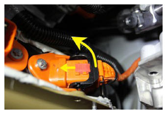 Courtesy of TESLA, INC. Courtesy of TESLA, INC.
|
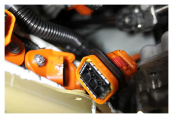 Courtesy of TESLA, INC. Courtesy of TESLA, INC.
|
- Loosen four center bolts securing HV battery
NOTE:
4x bolts, EP16, 23 N.m
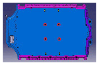 Courtesy of TESLA, INC. Courtesy of TESLA, INC.
|
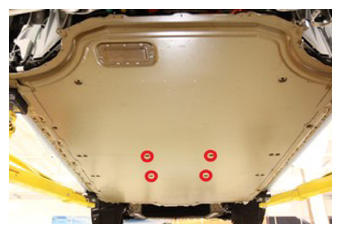 Courtesy of TESLA, INC. Courtesy of TESLA, INC.
|
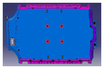
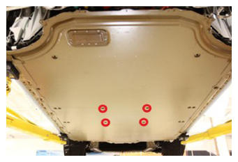
- Remove four center bolts securing HV battery with battery powered drill
NOTE:
4x bolts, EP16, 23 N.m
 Courtesy of TESLA, INC. Courtesy of TESLA, INC.
|
 Courtesy of TESLA, INC. Courtesy of TESLA, INC.
|
- Position battery table beneath vehicle
- Lower vehicle to table
NOTE:
Recommend assistance, Align table to vehicle and raise casters to level table if necessary
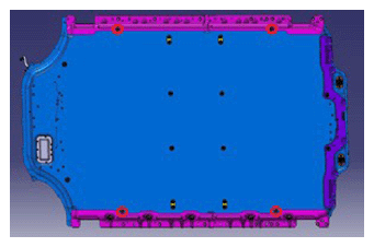
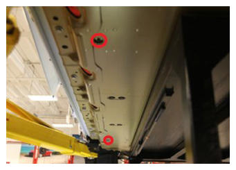
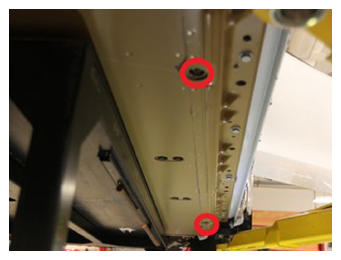
- Loosen M6 outer center bolts securing HV battery
NOTE:
4x bolts, EP14, 15 N.m
 Courtesy of TESLA, INC. Courtesy of TESLA, INC.
|
 Courtesy of TESLA, INC. Courtesy of TESLA, INC.
|
 Courtesy of TESLA, INC. Courtesy of TESLA, INC.
|
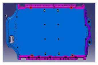
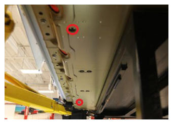
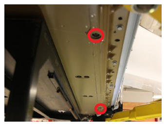
- Remove M6 outer center bolts securing HV battery with battery powered drill
NOTE:
4x bolts, EP14, 15 N.m
 Courtesy of TESLA, INC. Courtesy of TESLA, INC.
|
 Courtesy of TESLA, INC. Courtesy of TESLA, INC.
|
 Courtesy of TESLA, INC. Courtesy of TESLA, INC.
|
- Loosen remaining M8 outer bolts securing HV battery
NOTE:
12x bolts, EP16, 23 N.m
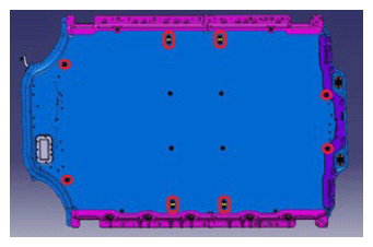 Courtesy of TESLA, INC. Courtesy of TESLA, INC.
|
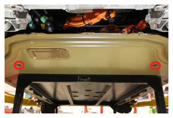 Courtesy of TESLA, INC. Courtesy of TESLA, INC.
|
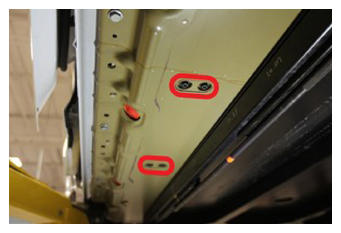 Courtesy of TESLA, INC. Courtesy of TESLA, INC.
|
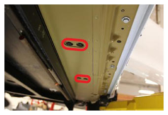 Courtesy of TESLA, INC. Courtesy of TESLA, INC.
|
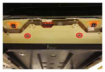 Courtesy of TESLA, INC. Courtesy of TESLA, INC.
|
- Remove remaining M8 outer bolts securing HV battery with battery powered drill
NOTE:
12x bolts, EP16, 23 N.m
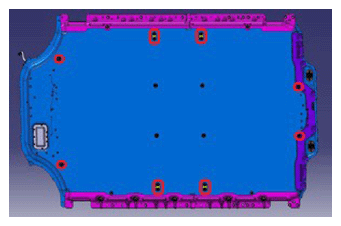 Courtesy of TESLA, INC. Courtesy of TESLA, INC.
|
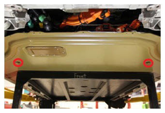 Courtesy of TESLA, INC. Courtesy of TESLA, INC.
|
 Courtesy of TESLA, INC. Courtesy of TESLA, INC.
|
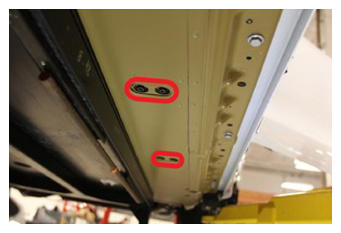 Courtesy of TESLA, INC. Courtesy of TESLA, INC.
|
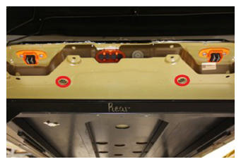 Courtesy of TESLA, INC. Courtesy of TESLA, INC.
|
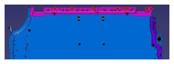
- Loosen LH rocker bolts
NOTE:
8x bolts, 15 mm, 35 N.m
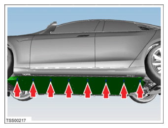 Courtesy of TESLA, INC. Courtesy of TESLA, INC.
|
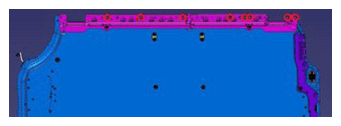 Courtesy of TESLA, INC. Courtesy of TESLA, INC.
|
- Remove LH rocker bolts with battery powered drill
NOTE:
8x bolts, 15 mm, 35 N.m
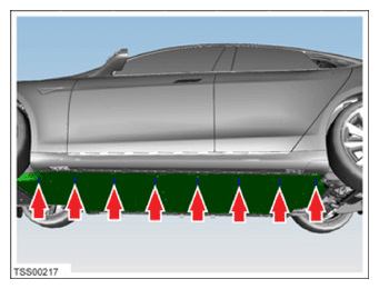 Courtesy of TESLA, INC. Courtesy of TESLA, INC.
|
 Courtesy of TESLA, INC. Courtesy of TESLA, INC.
|
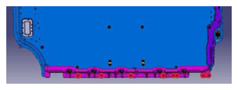
- Loosen RH rocker bolts
NOTE:
8x bolts, 15 mm, 35 N.m
 Courtesy of TESLA, INC. Courtesy of TESLA, INC.
|
 Courtesy of TESLA, INC. Courtesy of TESLA, INC.
|
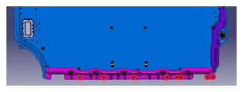
- Remove RH rocker bolts with battery powered drill
NOTE:
8x bolts, 15 mm, 35 N.m
 Courtesy of TESLA, INC. Courtesy of TESLA, INC.
|
 Courtesy of TESLA, INC. Courtesy of TESLA, INC.
|
- Raise vehicle off of HV battery
- Move battery away from vehicle
NOTE:
Recommend assistance
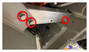
- Remove LH toeboard brace
NOTE:
3x bolts, 15 mm, 30 N.m
 Courtesy of TESLA, INC. Courtesy of TESLA, INC.
|
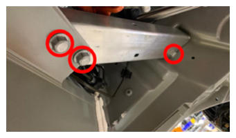
- Install LH toeboard brace
NOTE:
3x bolts, 15 mm, 30 N.m
 Courtesy of TESLA, INC. Courtesy of TESLA, INC.
|
- Position HV battery underneath vehicle
NOTE:
Recommend assistance
- Lower vehicle onto pack
NOTE:
Verify liftpads will not cause physical contact during lowering, Monitor components to prevent smashing or damage, Use alignment rods as required
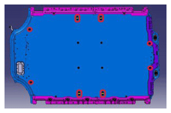
- Install M8 outer bolts with battery powered drill
NOTE:
12x bolts, EP16, 23 N.m, Start thread by hand, Flush down bolt, Do not over tighten bolts, Fully torque at later step
 Courtesy of TESLA, INC. Courtesy of TESLA, INC.
|
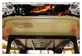 Courtesy of TESLA, INC. Courtesy of TESLA, INC.
|
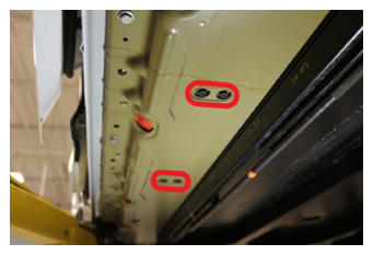 Courtesy of TESLA, INC. Courtesy of TESLA, INC.
|
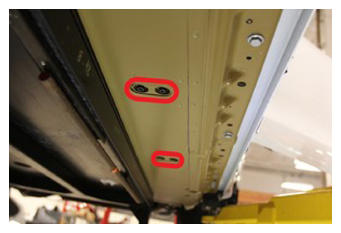 Courtesy of TESLA, INC. Courtesy of TESLA, INC.
|
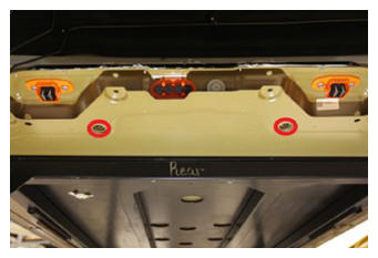 Courtesy of TESLA, INC. Courtesy of TESLA, INC.
|
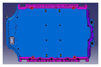
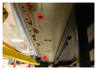
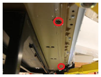
- Install M6 outer center bolts with battery powered drill
NOTE:
4x bolts, EP14, 15 N.m, Start thread by hand, Flush down bolt, Do not over tighten bolts, Fully torque at later step
 Courtesy of TESLA, INC. Courtesy of TESLA, INC.
|
 Courtesy of TESLA, INC. Courtesy of TESLA, INC.
|
 Courtesy of TESLA, INC. Courtesy of TESLA, INC.
|
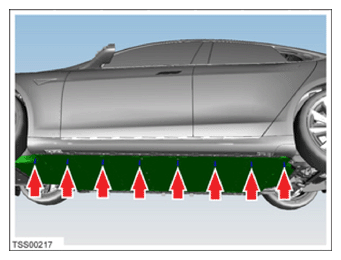
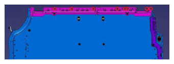
- Install LH rocker bolts with battery powered drill
NOTE:
8x bolts, 15 mm, 35 N.m, Start thread by hand, Flush down bolt, Do not over tighten bolts, Fully torque at later step
 Courtesy of TESLA, INC. Courtesy of TESLA, INC.
|
 Courtesy of TESLA, INC. Courtesy of TESLA, INC.
|
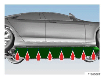
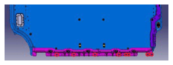
- Install RH rocker bolts with battery powered drill
NOTE:
8x bolts, 15 mm, 35 N.m, Start thread by hand, Flush down bolt, Do not over tighten bolts, Fully torque at later step
 Courtesy of TESLA, INC. Courtesy of TESLA, INC.
|
 Courtesy of TESLA, INC. Courtesy of TESLA, INC.
|
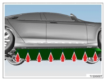
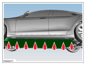
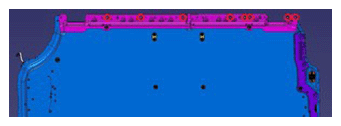
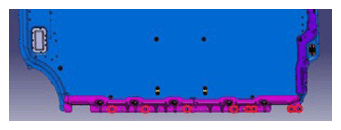
- Torque rocker HV battery bolts on both sides
NOTE:
16x bolts, 15 mm, 35 N.m
 Courtesy of TESLA, INC. Courtesy of TESLA, INC.
|
 Courtesy of TESLA, INC. Courtesy of TESLA, INC.
|
 Courtesy of TESLA, INC. Courtesy of TESLA, INC.
|
 Courtesy of TESLA, INC. Courtesy of TESLA, INC.
|
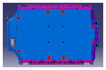
- Torque M8 outer bolts securing HV battery
NOTE:
12x bolts, EP16, 23 N.m
 Courtesy of TESLA, INC. Courtesy of TESLA, INC.
|
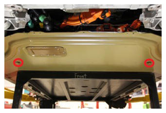 Courtesy of TESLA, INC. Courtesy of TESLA, INC.
|
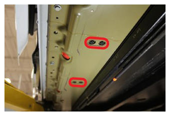 Courtesy of TESLA, INC. Courtesy of TESLA, INC.
|
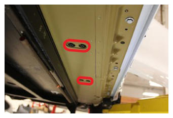 Courtesy of TESLA, INC. Courtesy of TESLA, INC.
|
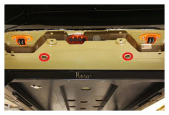 Courtesy of TESLA, INC. Courtesy of TESLA, INC.
|
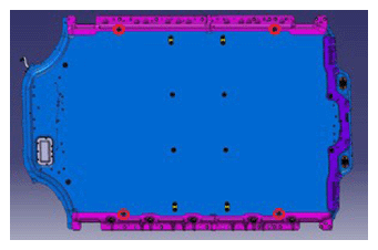
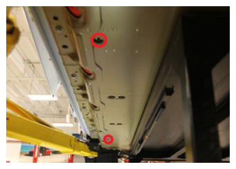
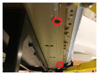
- Torque M6 outer center bolts
NOTE:
4 bolts, EP14, 15 N.m
 Courtesy of TESLA, INC. Courtesy of TESLA, INC.
|
 Courtesy of TESLA, INC. Courtesy of TESLA, INC.
|
 Courtesy of TESLA, INC. Courtesy of TESLA, INC.
|
- Raise vehicle and remove battery table
NOTE:
Recommend assistance
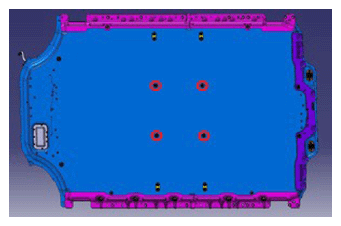
- Install four center bolts securing HV battery with battery powered drill
NOTE:
4x bolts, EP16, 23 N.m, Start thread by hand, Do not over tighten bolts, Fully torque at later step
 Courtesy of TESLA, INC. Courtesy of TESLA, INC.
|
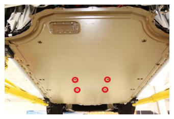 Courtesy of TESLA, INC. Courtesy of TESLA, INC.
|
- Torque the four center HV battery bolts
NOTE:
4x bolts, EP16, 23 N.m
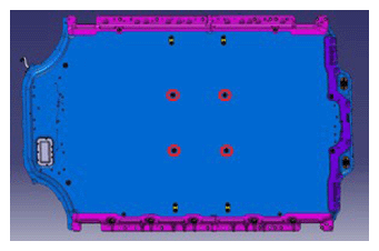 Courtesy of TESLA, INC. Courtesy of TESLA, INC.
|
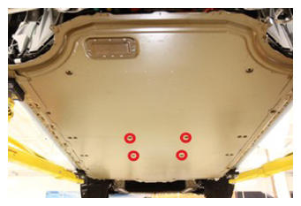 Courtesy of TESLA, INC. Courtesy of TESLA, INC.
|
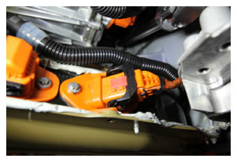
- Secure HV compressor connection to battery pack
NOTE:
1x connector, Verify lever is in the upright and open position, Carefully seat connector and allow lever to engage, Fully secure lever and verify red tab is locked
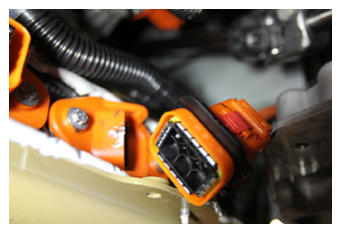 Courtesy of TESLA, INC. Courtesy of TESLA, INC.
|
 Courtesy of TESLA, INC. Courtesy of TESLA, INC.
|
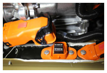
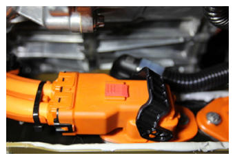
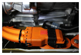
- Secure FDU HV harness connection to HV battery
NOTE:
1x connector, Verify lever is in the upright and open position, Carefully seat connector and allow lever to engage, Fully secure lever and verify red tab is locked, Do not damage any pins
 Courtesy of TESLA, INC. Courtesy of TESLA, INC.
|
 Courtesy of TESLA, INC. Courtesy of TESLA, INC.
|
 Courtesy of TESLA, INC. Courtesy of TESLA, INC.
|
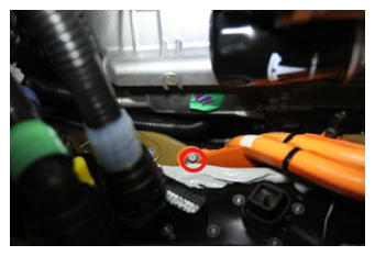
- Install bolt securing FDU HV harness to HV battery
NOTE:
1x bolt, 8 mm, 5.5 N.m
 Courtesy of TESLA, INC. Courtesy of TESLA, INC.
|
- Position coolant drain container under the front of the vehicle to catch vehicle coolant
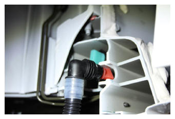
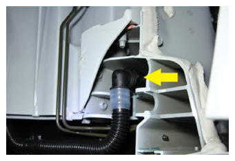
- Secure LH front sill coolant hose
NOTE:
1x hose clip, 2x hose plugs, Remove plugs and secure hose. Perform push-pull-push test
 Courtesy of TESLA, INC. Courtesy of TESLA, INC.
|
 Courtesy of TESLA, INC. Courtesy of TESLA, INC.
|
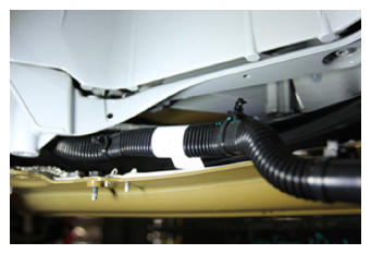
- Secure LH sill coolant hose clips to body
NOTE:
2x clips
 Courtesy of TESLA, INC. Courtesy of TESLA, INC.
|
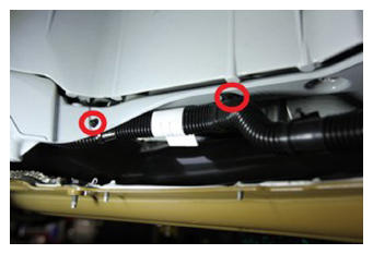 Courtesy of TESLA, INC. Courtesy of TESLA, INC.
|
- Install bolt securing ground strap to body
NOTE:
1x bolt, 10 mm, 10 N.m
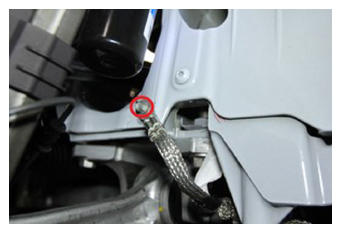 Courtesy of TESLA, INC. Courtesy of TESLA, INC.
|
- Secure clips on LH front wheel house liner
NOTE:
2x clips, Return to position
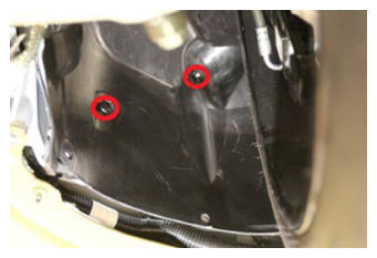 Courtesy of TESLA, INC. Courtesy of TESLA, INC.
|
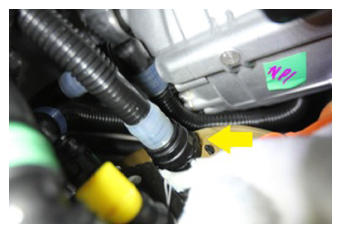
- Secure PCS inlet hose to HV battery
NOTE:
1x hose clip, 2x hose plugs, Remove plugs and secure hose, Use a shop rag to prevent coolant seepage into connection, Perform push-pull-push test
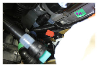 Courtesy of TESLA, INC. Courtesy of TESLA, INC.
|
 Courtesy of TESLA, INC. Courtesy of TESLA, INC.
|
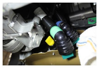
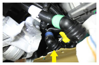
- Secure battery supply coolant hose to HV battery
NOTE:
1x hose clip, 2x hose plugs, Remove plugs and secure hose, Perform push-pull-push test
 Courtesy of TESLA, INC. Courtesy of TESLA, INC.
|
 Courtesy of TESLA, INC. Courtesy of TESLA, INC.
|
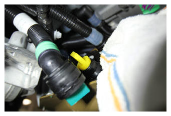
- Secure 3 way valve coolant hose to HV battery
NOTE:
1x hose clip, 2x hose plugs, Remove plugs and secure hose, Perform push-pull-push test, Remove shop rag when finished
 Courtesy of TESLA, INC. Courtesy of TESLA, INC.
|
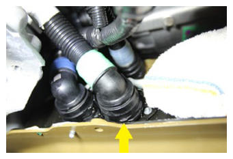 Courtesy of TESLA, INC. Courtesy of TESLA, INC.
|
- Remove coolant drain container from underneath vehicle
- Secure power connector to HV battery
NOTE:
1x connector, Engage red locking tab
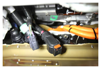 Courtesy of TESLA, INC. Courtesy of TESLA, INC.
|
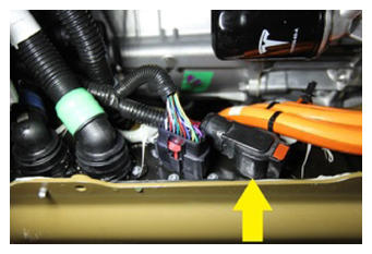 Courtesy of TESLA, INC. Courtesy of TESLA, INC.
|
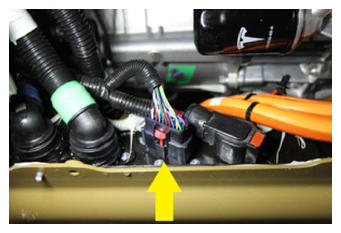
- Secure logic connector to HV battery
NOTE:
1x connector, Engage red locking tab
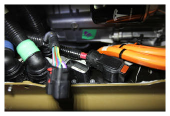 Courtesy of TESLA, INC. Courtesy of TESLA, INC.
|
 Courtesy of TESLA, INC. Courtesy of TESLA, INC.
|
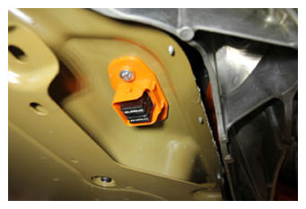
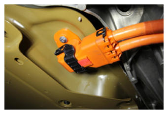
- Secure RDU HV harness to battery pack
NOTE:
1x connector, Verify lever is in the upright and open position, Carefully seat connector and allow lever to engage, Fully secure lever and verify red tab is locked, Do not damage any pins
 Courtesy of TESLA, INC. Courtesy of TESLA, INC.
|
 Courtesy of TESLA, INC. Courtesy of TESLA, INC.
|
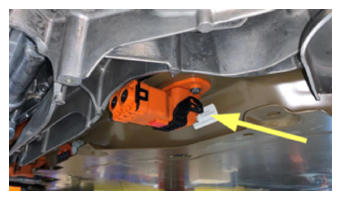
- Secure PRDU dummy plug to HV battery pack
NOTE:
1x connector, Fully seat connector body, then engage locking latch
 Courtesy of TESLA, INC. Courtesy of TESLA, INC.
|
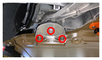
- Install LH shear plate
NOTE:
1x nut, 15 mm, 60 N.m, 2x bolts, 10 mm, 30 N.m
 Courtesy of TESLA, INC. Courtesy of TESLA, INC.
|
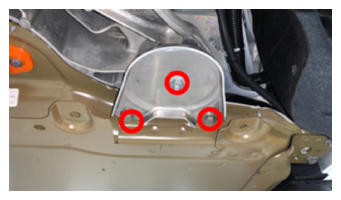
- Install RH shear plate
NOTE:
1x nut, 15 mm, 60 N.m, 2x bolts, 10 mm, 30 N.m
 Courtesy of TESLA, INC. Courtesy of TESLA, INC.
|
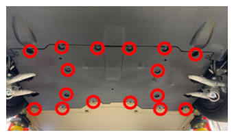
- Apply Loctite 222 onto mid aero shield bolts and install fasteners securing mid aero shield to vehicle
NOTE:
16x bolts, 10 mm, 6 N.m
 Courtesy of TESLA, INC. Courtesy of TESLA, INC.
|
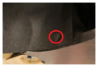
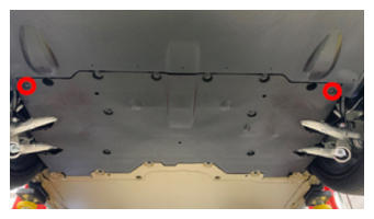
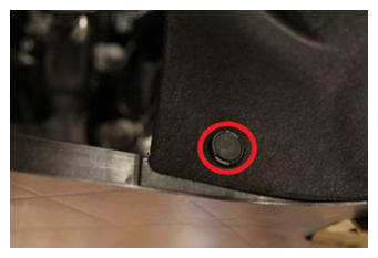
- Install clips securing mid aero shield
NOTE:
4x push clips
 Courtesy of TESLA, INC. Courtesy of TESLA, INC.
|
 Courtesy of TESLA, INC. Courtesy of TESLA, INC.
|
 Courtesy of TESLA, INC. Courtesy of TESLA, INC.
|
- Position lifting tool and front subframe under vehicle for installation
- Connect shop air supply to the powertrain table
- Raise front subframe into position to be installed
NOTE:
Recommend assistance, Use caution and maneuver harnesses and knuckles so that subframe assembly is installed correctly, Guide damper forks around links
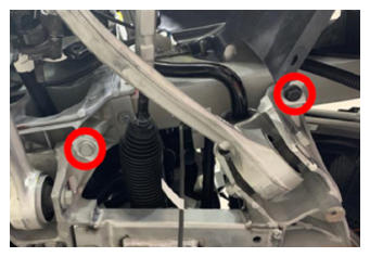
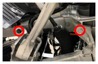
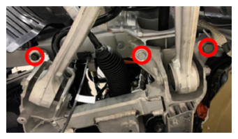
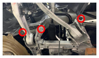
- Hand-tighten the bolts located at the front of the front subframe.
NOTE:
Depending on the vehicle manufacture date, the front-most bolts might be as follows (16 mm or 18 mm):
- M12 1.75 x 75 bolt (1063242-00-B) and M12 x 24 x 2.5 washer (1103852-00-A)
- M12 1.75 x 115 bolt (1608611-00-C)
NOTE:
Hand-tighten the bolts, and then use a battery powered drill to continue fastening the bolts. Do not tighten fully. Fully tighten the bolts at later step.
 Courtesy of TESLA, INC. Courtesy of TESLA, INC.
|
 Courtesy of TESLA, INC. Courtesy of TESLA, INC.
|
 Courtesy of TESLA, INC. Courtesy of TESLA, INC.
|
- Lower the powertrain table and remove it from under the vehicle
NOTE:
Release ratchet strap from subframe fixture
- Disconnect shop air supply from the powertrain table
- Remove the subframe lifting tool from vehicle
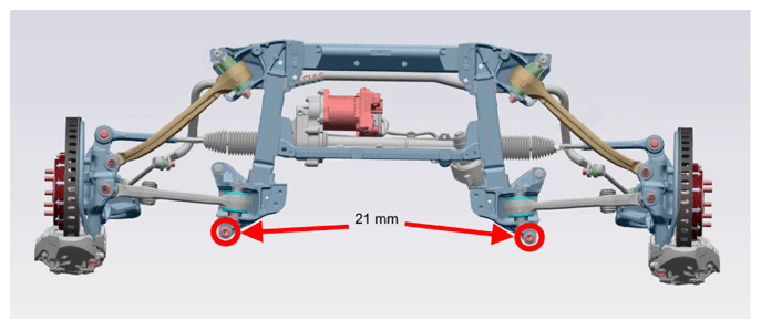
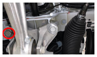
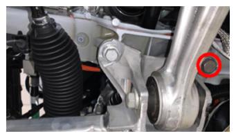
- Hand-tighten the rear bolts of the front subframe.
NOTE:
21 mm. Depending on the vehicle manufacture date, the rear bolts might be as follows:
- M14 2.0 x 58 (1133941-00-C)
- M14 2.0 x 67 (1638540-00-A)
NOTE:
Hand-tighten the bolts, and then use a battery powered drill to continue fastening the bolts. Do not tighten fully. Fully tighten the bolts at later step.
 Courtesy of TESLA, INC. Courtesy of TESLA, INC.
|
 Courtesy of TESLA, INC. Courtesy of TESLA, INC.
|
 Courtesy of TESLA, INC. Courtesy of TESLA, INC.
|
- Tighten the front subframe bolts.
NOTE:
16 mm or 18 mm bolts: 80 N.m
NOTE:
21 mm bolts: Depending on the vehicle manufacture date, the torque rating of the bolts is as follows:
- M14 2.0 x 58 (1133941-00-C): 115 N.m
- M14 2.0 x 67 (1638540-00-A): 145 N.m
 Courtesy of TESLA, INC.
 Courtesy of TESLA, INC. Courtesy of TESLA, INC.
|
 Courtesy of TESLA, INC. Courtesy of TESLA, INC.
|
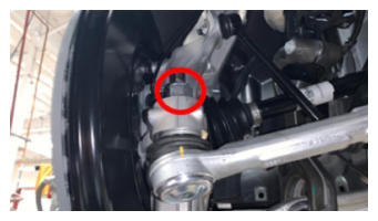
- Position RH tie rod and install nut
NOTE:
1x nyloc nut, 21 mm, 102 N.m, Install new nut
 Courtesy of TESLA, INC. Courtesy of TESLA, INC.
|
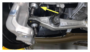
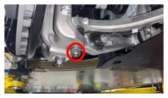
- Position RH fore link to knuckle assemble and install nut
NOTE:
1x nyloc nut, 22 mm, 180 N.m, Install new nut, Counter hold stud with T45 socket
 Courtesy of TESLA, INC. Courtesy of TESLA, INC.
|
 Courtesy of TESLA, INC. Courtesy of TESLA, INC.
|
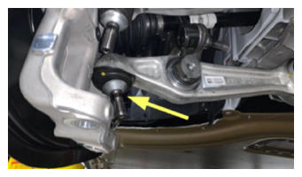
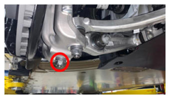
- Position RH aft link to knuckle assemble and install nut
NOTE:
1x nyloc nut, 22 mm, 180 N.m, Install new nut, Counter hold stud with T45 socket
 Courtesy of TESLA, INC. Courtesy of TESLA, INC.
|
 Courtesy of TESLA, INC. Courtesy of TESLA, INC.
|
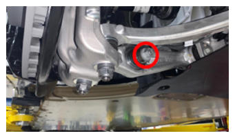
- Install bolt and nut securing RH front air spring module to front lower aft link hand tight
NOTE:
1x bolt, 21 mm, 1x nut, 21 mm, 140 N.m, Torque at later step
 Courtesy of TESLA, INC. Courtesy of TESLA, INC.
|
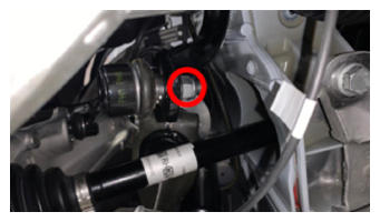
- Position stabar and install nut securing RH endlink to stabar assembly
NOTE:
1x nyloc nut, 15 mm, 70 N.m, Install new nut, Counter hold stud with 5 mm socket
 Courtesy of TESLA, INC. Courtesy of TESLA, INC.
|
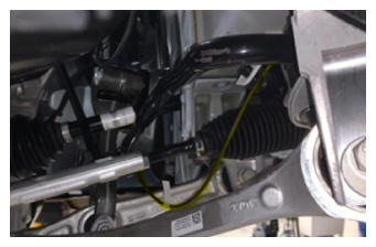
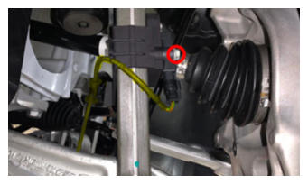
- Route ANC sensor and damper bracket and secure to RH front air spring module
NOTE:
1x bolt, 10 mm, 6 N.m, Harness routes above lower links and below tie rod/axle
 Courtesy of TESLA, INC. Courtesy of TESLA, INC.
|
 Courtesy of TESLA, INC. Courtesy of TESLA, INC.
|
- Install RH front wheel
NOTE:
5x nuts, 21 mm, 175 N.m, Start lug nuts by hand before using power tool
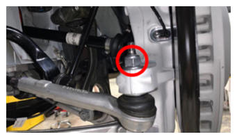
- Position LH tie rod and install nut
NOTE:
1x nyloc nut, 21 mm, 102 N.m, Install new nut
 Courtesy of TESLA, INC. Courtesy of TESLA, INC.
|
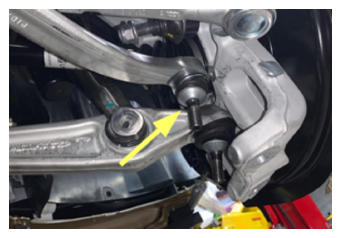
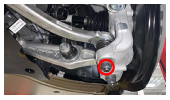
- Position LH fore link to knuckle assemble and install nut
NOTE:
1x nyloc nut, 22 mm, 180 N.m, Install new nut, Counter hold stud with T45 socket
 Courtesy of TESLA, INC. Courtesy of TESLA, INC.
|
 Courtesy of TESLA, INC. Courtesy of TESLA, INC.
|
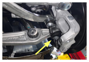
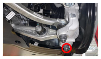
- Position LH aft link to knuckle assemble and install nut
NOTE:
1x nyloc nut, 22 mm, 180 N.m, Install new nut, Counter hold stud with T45 socket
 Courtesy of TESLA, INC. Courtesy of TESLA, INC.
|
 Courtesy of TESLA, INC. Courtesy of TESLA, INC.
|
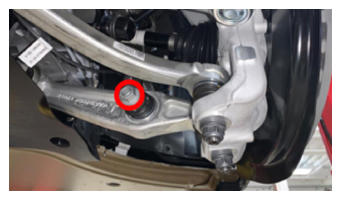
- Install bolt and nut securing LH front air spring module to front lower aft link hand tight
NOTE:
1x bolt, 21 mm, 1x nut, 21 mm, 140 N.m, Torque at later step
 Courtesy of TESLA, INC. Courtesy of TESLA, INC.
|
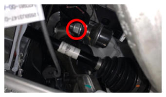
- Position stabar and install nut securing LH endlink to stabar assembly
NOTE:
1x nyloc nut, 15 mm, 70 N.m, Install new nut, Counter hold stud with 5 mm socket
 Courtesy of TESLA, INC. Courtesy of TESLA, INC.
|
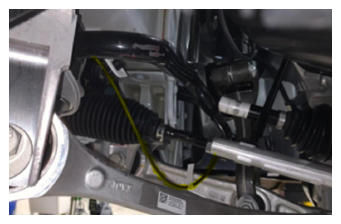
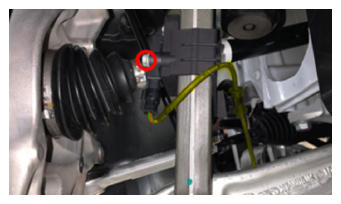
- Route ANC sensor and damper bracket and secure to LH front air spring module
NOTE:
1x bolt, 10 mm, 6 N.m, Harness routes above lower links and below tie rod/axle
 Courtesy of TESLA, INC. Courtesy of TESLA, INC.
|
 Courtesy of TESLA, INC. Courtesy of TESLA, INC.
|
- Install LH front wheel
NOTE:
5x nuts, 21 mm, 175 N.m, Start lug nuts by hand before using power tool
- Raise vehicle fully and lower lift onto locks
NOTE:
Set vehicle to comfortable working height, Make sure there's an audible click of the locks on both sides before lowering, otherwise vehicle may tilt to the side
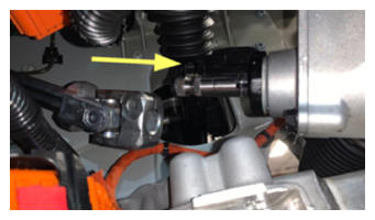
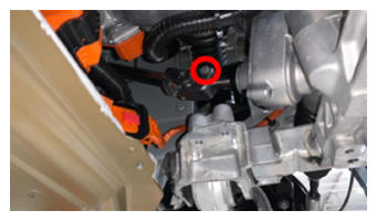
- Slide the lower electric steering column onto the steering gear and install the fastener
NOTE:
1x bolt, 13 mm, 30 N.m
 Courtesy of TESLA, INC. Courtesy of TESLA, INC.
|
 Courtesy of TESLA, INC. Courtesy of TESLA, INC.
|
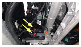
- Connect the logic connectors for the steering rack
NOTE:
2x electrical connectors, 2-way connectors, Engage the grey lock after the connector is fully seated
 Courtesy of TESLA, INC. Courtesy of TESLA, INC.
|
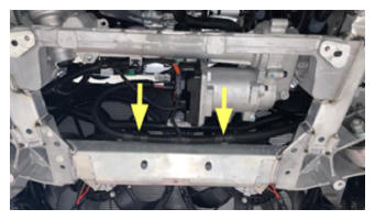
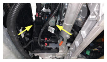
- Connect steering rack connectors
NOTE:
2x connectors, 2 stage locking connectors, Ensure the locking tab is engaged after an audible click is heard when connecting
 Courtesy of TESLA, INC. Courtesy of TESLA, INC.
|
 Courtesy of TESLA, INC. Courtesy of TESLA, INC.
|
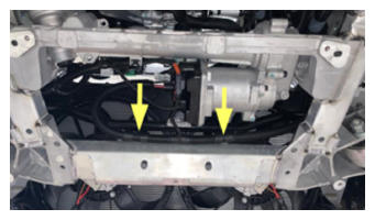
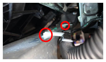
- Secure frunk harness to subframe
NOTE:
2x clips
 Courtesy of TESLA, INC. Courtesy of TESLA, INC.
|
 Courtesy of TESLA, INC. Courtesy of TESLA, INC.
|
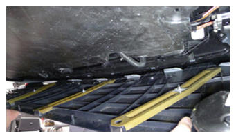
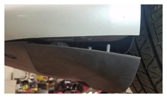
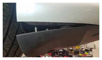
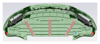
- Install valance onto front fascia assembly
NOTE:
2x nuts, 10 mm, 3 N.m, Recommend assistance, Interlock valance tabs with fascia tabs, Clip in LH and RH corners of valance onto fascia
 Courtesy of TESLA, INC. Courtesy of TESLA, INC.
|
 Courtesy of TESLA, INC. Courtesy of TESLA, INC.
|
 Courtesy of TESLA, INC. Courtesy of TESLA, INC.
|
 Courtesy of TESLA, INC. Courtesy of TESLA, INC.
|
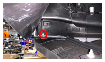 Courtesy of TESLA, INC. Courtesy of TESLA, INC.
|
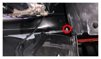 Courtesy of TESLA, INC. Courtesy of TESLA, INC.
|
- Install clips that secure valance to front fascia assembly
NOTE:
8x push clips, Hold fascia tabs flush with valance if necessary
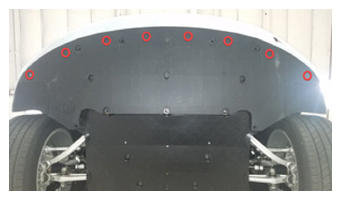 Courtesy of TESLA, INC. Courtesy of TESLA, INC.
|
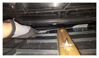 Courtesy of TESLA, INC. Courtesy of TESLA, INC.
|
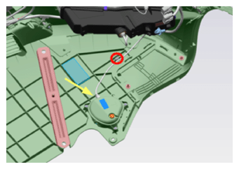
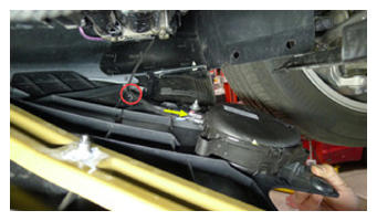
- Install pedestrian warning speaker connector
NOTE:
1x connector, Engage locking tab, 1x edge clip, Located on RH ride of front fascia valance
 Courtesy of TESLA, INC. Courtesy of TESLA, INC.
|
 Courtesy of TESLA, INC. Courtesy of TESLA, INC.
|
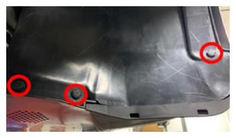
- Install clips securing RH wheelhouse liner to valance and front fascia
NOTE:
3x push clips
 Courtesy of TESLA, INC. Courtesy of TESLA, INC.
|
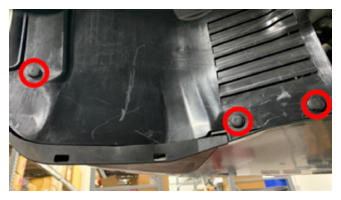
- Install clips securing LH wheelhouse liner to valance and front fascia
NOTE:
3x push clips
 Courtesy of TESLA, INC. Courtesy of TESLA, INC.
|
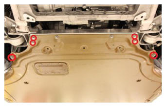
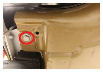
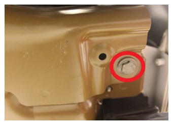
- Position front skid plate for installation and thread in all bolts
NOTE:
4x bolts, 15 mm, 70 N.m, 2x bolts, 15 mm, 60 N.m, 2x bolts, 15 mm, 30 N.m, Torque at later step
 Courtesy of TESLA, INC. Courtesy of TESLA, INC.
|
 Courtesy of TESLA, INC. Courtesy of TESLA, INC.
|
 Courtesy of TESLA, INC. Courtesy of TESLA, INC.
|
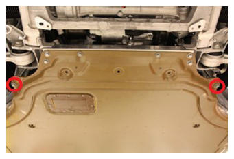
- Torque bolts securing front skid plate to body casting
NOTE:
2x bolts, 15 mm, 60 N.m
 Courtesy of TESLA, INC. Courtesy of TESLA, INC.
|
- Torque bolts securing front skid plate to body sill
NOTE:
2x bolts, 15 mm, 30 N.m
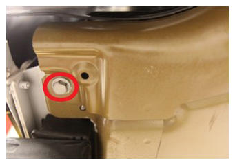 Courtesy of TESLA, INC. Courtesy of TESLA, INC.
|
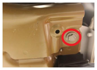 Courtesy of TESLA, INC. Courtesy of TESLA, INC.
|
- Torque bolts securing front skid plate to front subframe
NOTE:
4x bolts, 15 mm, 70 N.m,
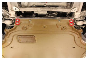 Courtesy of TESLA, INC. Courtesy of TESLA, INC.
|
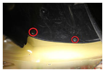
- Secure clips securing wheel house liner to front skid plate
NOTE:
4x clips
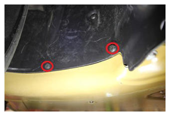 Courtesy of TESLA, INC. Courtesy of TESLA, INC.
|
 Courtesy of TESLA, INC. Courtesy of TESLA, INC.
|
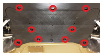
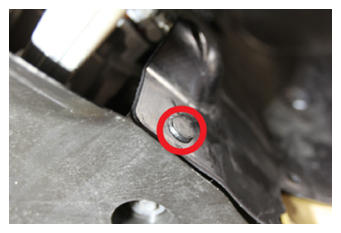
- Apply Loctite 222 onto front aero shield bolts and install fasteners securing front aero shield to vehicle
NOTE:
9x bolts, 10 mm, 6 N.m
 Courtesy of TESLA, INC. Courtesy of TESLA, INC.
|
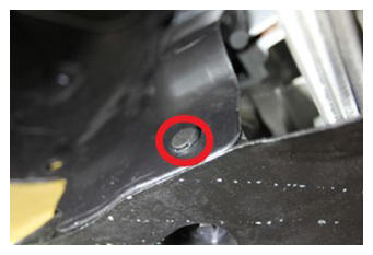
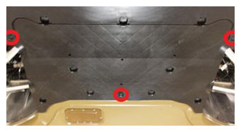
- Install clips securing front aero shield
NOTE:
5x push clips
 Courtesy of TESLA, INC. Courtesy of TESLA, INC.
|
 Courtesy of TESLA, INC. Courtesy of TESLA, INC.
|
 Courtesy of TESLA, INC. Courtesy of TESLA, INC.
|
- Lower vehicle until tires are touching the ground
NOTE:
Raise lift off locks, then hold lock release lever to keep locks free while vehicle is lowered
- Torque LH front wheel
NOTE:
5x nuts, 21 mm, 175 N.m
- Torque RH front wheel
NOTE:
5x nuts, 21 mm, 175 N.m
- Install RH front lug nut covers
NOTE:
5x covers
- Install LH front lug nut covers
NOTE:
5x covers
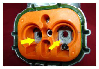
- Clean busbar HV connector contact surface of residual Penetrox
NOTE:
Allow 1 minute dry time after removing Penetrox, It is necessary to clean HV connector during re-use of busbar
 Courtesy of TESLA, INC. Courtesy of TESLA, INC.
|
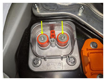
- Clean HV connector contact surface of residual Penetrox
NOTE:
Allow 1 minute dry time after removing Penetrox, New busbar comes with Penetrox applied to HV connector
 Courtesy of TESLA, INC. Courtesy of TESLA, INC.
|
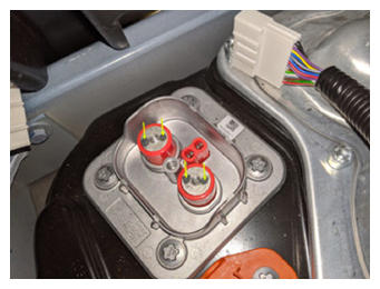
- Apply Penetrox onto HV connector joints
NOTE:
Apply 2 drops of Penetrox A-13 about 5 mm in diameter to either side of the hole on both leads, Spread evenly to verify the contact surface is fully covered
 Courtesy of TESLA, INC. Courtesy of TESLA, INC.
|
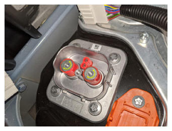 Courtesy of TESLA, INC. Courtesy of TESLA, INC.
|
- Secure busbar onto HV header and install bolts
NOTE:
2x bolts, 10 mm, 9 N.m
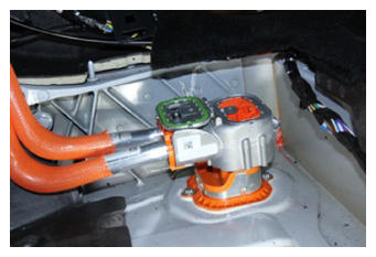 Courtesy of TESLA, INC. Courtesy of TESLA, INC.
|
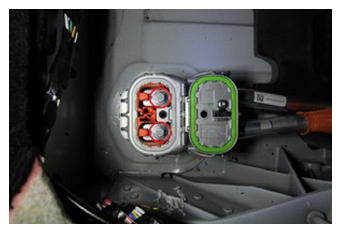 Courtesy of TESLA, INC. Courtesy of TESLA, INC.
|
- Inspect HV insulating gloves
NOTE:
Check gloves for damage prior to use
- Put on HV insulating gloves and leather over gloves
- Perform Hioki resistance test at each HV joint from HV busbar lead to bolt head
NOTE:
2x HV joints, When using Hioki tester, verify the meter has been properly adjusted and set prior to usage. The acceptable resistance is between 0.050 mΩ (50 μΩ) and 0.195 mΩ (195 μΩ). If the resistance is greater than 0.195 mΩ (195 μΩ), stop work and escalate the Toolbox session. If the resistance is lower than 0.050 mΩ (50 μΩ), reposition the probes and measure again. If the resistance is repeatedly between 0.00 mΩ and 0.050 mΩ (50 μΩ), hioki test passed, proceed to next step
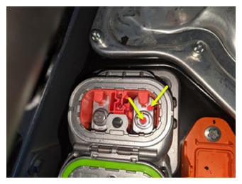 Courtesy of TESLA, INC. Courtesy of TESLA, INC.
|
- Remove the leather glove protectors and HV insulating gloves
- Install fastener securing busbar cover access door
NOTE:
1x bolt, 10 mm, 9 N.m
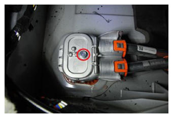 Courtesy of TESLA, INC. Courtesy of TESLA, INC.
|
- Install busbar header foam block
 Courtesy of TESLA, INC. Courtesy of TESLA, INC.
|
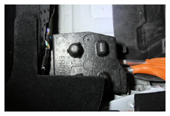 Courtesy of TESLA, INC. Courtesy of TESLA, INC.
|
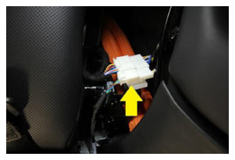
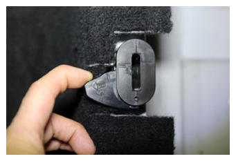
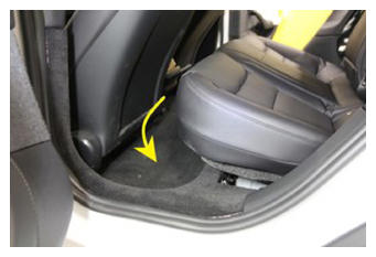
- Install 2nd row seat cushion assembly
NOTE:
2x clips, 2x connectors, Secure connections and slide seat belt buckles through the seat cushion, Engage clips
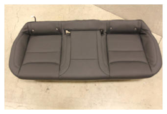 Courtesy of TESLA, INC. Courtesy of TESLA, INC.
|
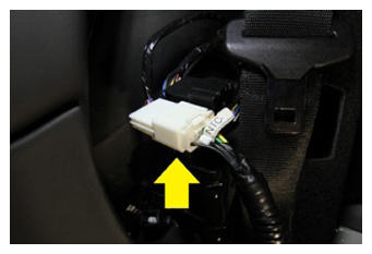 Courtesy of TESLA, INC. Courtesy of TESLA, INC.
|
 Courtesy of TESLA, INC. Courtesy of TESLA, INC.
|
 Courtesy of TESLA, INC. Courtesy of TESLA, INC.
|
 Courtesy of TESLA, INC. Courtesy of TESLA, INC.
|
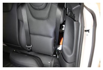
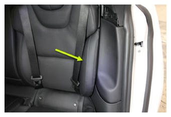
- Install LH side bolster trim
NOTE:
1x clip, 1x tab, Replace clip if damaged, Hook bottom portion and then secure the top
 Courtesy of TESLA, INC. Courtesy of TESLA, INC.
|
 Courtesy of TESLA, INC. Courtesy of TESLA, INC.
|
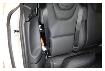
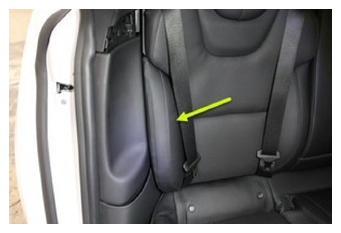
- Install RH side bolster trim
NOTE:
1x clip, 1x tab, Replace clip if damaged, Hook bottom portion and then secure the top
 Courtesy of TESLA, INC. Courtesy of TESLA, INC.
|
 Courtesy of TESLA, INC. Courtesy of TESLA, INC.
|
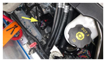
- Connect FDU harness to frunk harness
NOTE:
1x connector
 Courtesy of TESLA, INC. Courtesy of TESLA, INC.
|
- Place empty coolant container into front storage area
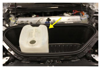 Courtesy of TESLA, INC. Courtesy of TESLA, INC.
|
- Fill container with at least 15L of coolant
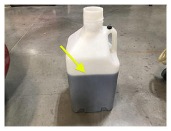 Courtesy of TESLA, INC. Courtesy of TESLA, INC.
|
- Place filled coolant container into front storage area
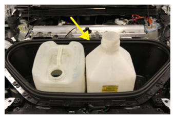 Courtesy of TESLA, INC. Courtesy of TESLA, INC.
|
- Remove coolant bottle cap
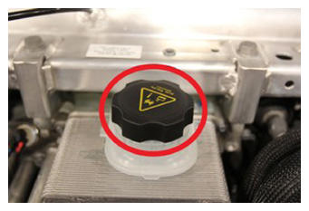 Courtesy of TESLA, INC. Courtesy of TESLA, INC.
|
- Install vacuum refill cap onto coolant bottle assembly
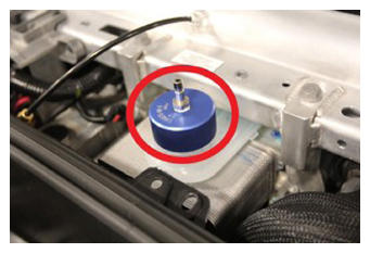 Courtesy of TESLA, INC. Courtesy of TESLA, INC.
|
- Setup coolant refill tool
NOTE:
Verify all valves on refill tool are in the closed position, See image for clarity
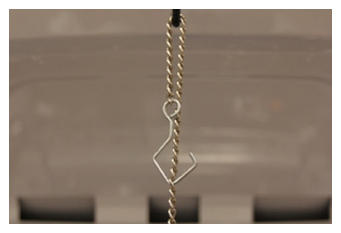 Courtesy of TESLA, INC. Courtesy of TESLA, INC.
|
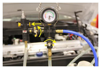 Courtesy of TESLA, INC. Courtesy of TESLA, INC.
|
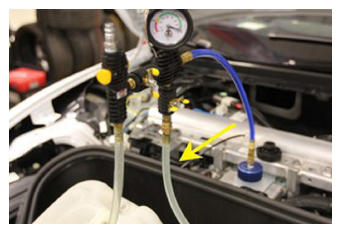
- Install vacuum refill hose into refill cap on coolant bottle
NOTE:
Perform push-pull-push test to verify hose is fully installed
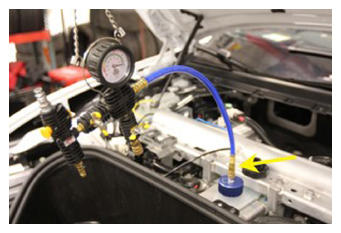 Courtesy of TESLA, INC. Courtesy of TESLA, INC.
|
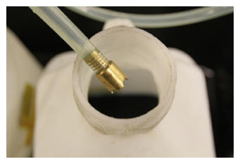
- Place refill hose inside filled coolant container
NOTE:
Make sure hose end is fully submerged into coolant
 Courtesy of TESLA, INC. Courtesy of TESLA, INC.
|
 Courtesy of TESLA, INC. Courtesy of TESLA, INC.
|
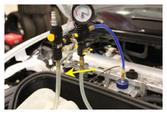
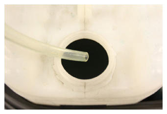
- Position overflow hose into empty container
 Courtesy of TESLA, INC. Courtesy of TESLA, INC.
|
 Courtesy of TESLA, INC. Courtesy of TESLA, INC.
|
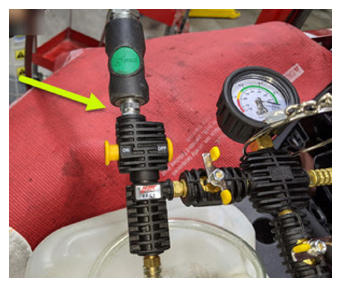
- Connect shop air supply to coolant refill tool
NOTE:
If not already done, Verify refill valve is set to off
 Courtesy of TESLA, INC. Courtesy of TESLA, INC.
|
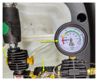
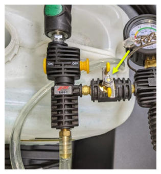
- Open air inlet valve to draw a vacuum, Once gauge stabilizes, Fully close valve
NOTE:
Gauge stabilizes roughly (60-70 cmHg), Vacuum should not drop after the valves are closed
 Courtesy of TESLA, INC. Courtesy of TESLA, INC.
|
 Courtesy of TESLA, INC. Courtesy of TESLA, INC.
|
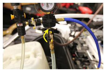
- Slowly open the refill valve to allow coolant to be drawn into the system
NOTE:
Make sure hose end of refill hose is fully submerged during entire process
 Courtesy of TESLA, INC. Courtesy of TESLA, INC.
|
- Once the gauge reads zero, close the coolant refill valve
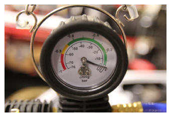 Courtesy of TESLA, INC. Courtesy of TESLA, INC.
|
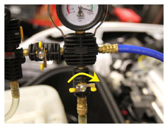 Courtesy of TESLA, INC. Courtesy of TESLA, INC.
|
- Disconnect shop air supply from coolant refill tool
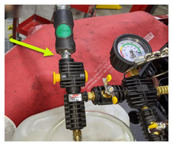 Courtesy of TESLA, INC. Courtesy of TESLA, INC.
|
- Remove coolant refill hose from coolant container
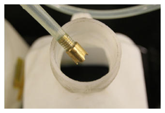 Courtesy of TESLA, INC. Courtesy of TESLA, INC.
|
- Remove coolant overflow hose from coolant container
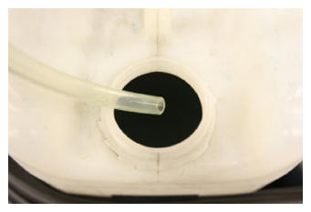 Courtesy of TESLA, INC. Courtesy of TESLA, INC.
|
- Remove vacuum refill hose from refill cap on coolant bottle
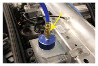 Courtesy of TESLA, INC. Courtesy of TESLA, INC.
|
- Remove coolant refill tool from vehicle
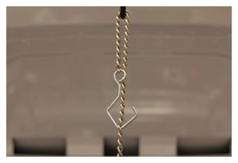 Courtesy of TESLA, INC. Courtesy of TESLA, INC.
|
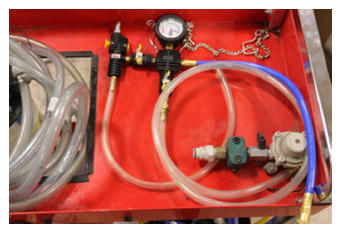 Courtesy of TESLA, INC. Courtesy of TESLA, INC.
|
- Remove both coolant containers from inside underhood area
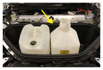 Courtesy of TESLA, INC. Courtesy of TESLA, INC.
|
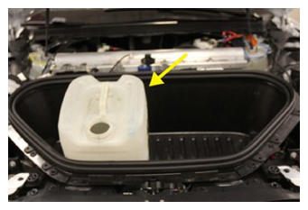 Courtesy of TESLA, INC. Courtesy of TESLA, INC.
|
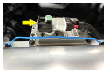
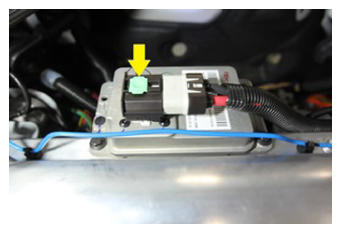
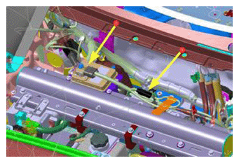
- Connect First Responder Loop and LV battery connector
NOTE:
2x connectors Secure FRL first, Seat LV battery connection and push black connector lock inwards to secure, Engage grey locking tab when fully seated
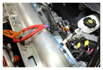 Courtesy of TESLA, INC. Courtesy of TESLA, INC.
|
 Courtesy of TESLA, INC. Courtesy of TESLA, INC.
|
 Courtesy of TESLA, INC. Courtesy of TESLA, INC.
|
 Courtesy of TESLA, INC. Courtesy of TESLA, INC.
|
- Using laptop connect to vehicle with ethernet diag kit and Toolbox 3
- Select 'Actions/Autodiag' tab and search for ' Purge'
- Select 'TEST_VCFRONT_X_THERMAL-COOLANT-AIR-PURGE', click 'Run', and allow routine to complete
NOTE:
Make sure vehicle is not in drive state, Plan is still running despite the stop message, Coolant pumps will be audible, Test lasts approximately 10 mins, Putting vehicle into drive state will stop this routine, Monitor levels as required
- Select 'Actions/Autodiag' and search for 'Thermal'
- Select 'TEST-SELF_VCFRONT_X_HEAT-PUMP-THERMAL-PERFORMANCE', click 'Run', and allow routine to complete
NOTE:
Select 'X' at top right of window to close once complete
- Disconnect Toolbox 3 from vehicle and remove laptop and ethernet diag kit
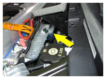
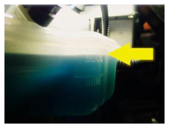
- Inspect coolant level and top off as necessary
NOTE:
Ensure that the fluid level is at the Max line, Top off fluid as required
 Courtesy of TESLA, INC. Courtesy of TESLA, INC.
|
 Courtesy of TESLA, INC. Courtesy of TESLA, INC.
|
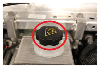
- Install coolant bottle cap
 Courtesy of TESLA, INC. Courtesy of TESLA, INC.
|
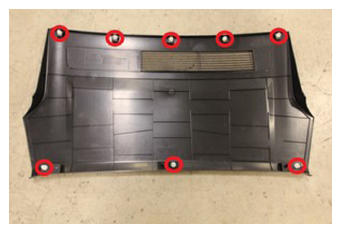
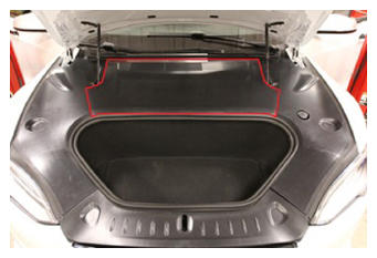
- Install rear underhood apron
NOTE:
8x clips
 Courtesy of TESLA, INC. Courtesy of TESLA, INC.
|
 Courtesy of TESLA, INC. Courtesy of TESLA, INC.
|
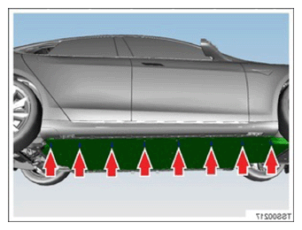
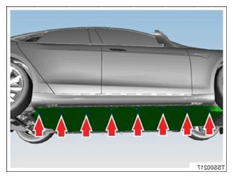
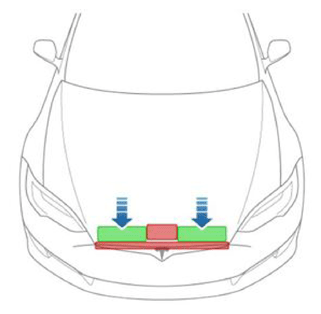
- Close hood
NOTE:
Press firmly in green highlighted areas (see image), Damage may result from pressure elsewhere on hood
 Courtesy of TESLA, INC. Courtesy of TESLA, INC.
|
- Remove vehicle from lift
NOTE:
Lower rack arms fully and remove them from under vehicle, Remove air suspension from "Jack Mode"
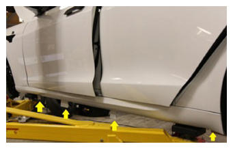
- Install LH rocker panel onto vehicle
NOTE:
Secure at front and rear fenders, Be sure to insert rocker above jack pads
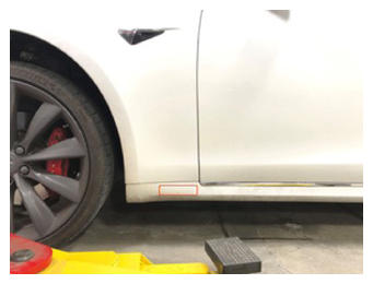 Courtesy of TESLA, INC. Courtesy of TESLA, INC.
|
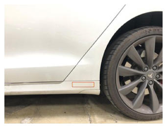 Courtesy of TESLA, INC. Courtesy of TESLA, INC.
|
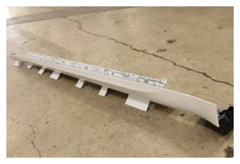 Courtesy of TESLA, INC. Courtesy of TESLA, INC.
|
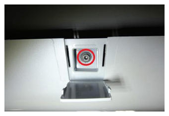
- Install bolts securing LH rocker panel to body
NOTE:
7x upper bolts, 10 mm, 3 N.m, 4x lower bolts, 10 mm, 3 N.m
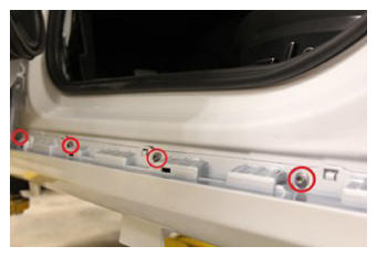 Courtesy of TESLA, INC. Courtesy of TESLA, INC.
|
 Courtesy of TESLA, INC. Courtesy of TESLA, INC.
|
 Courtesy of TESLA, INC. Courtesy of TESLA, INC.
|
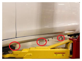
- Secure covers on bottom edge of LH rocker panel
NOTE:
3x covers
 Courtesy of TESLA, INC. Courtesy of TESLA, INC.
|
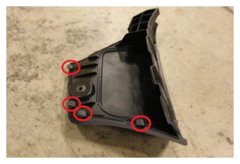
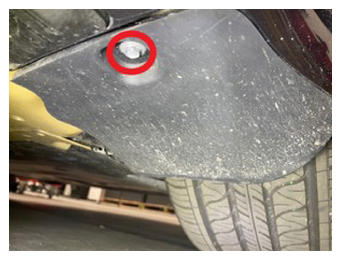
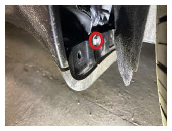
- Install LH rear wheel fairing and secure bolts
NOTE:
2x bolt, 8 mm, 2.85 N.m, 5x tabs
 Courtesy of TESLA, INC. Courtesy of TESLA, INC.
|
 Courtesy of TESLA, INC. Courtesy of TESLA, INC.
|
 Courtesy of TESLA, INC. Courtesy of TESLA, INC.
|
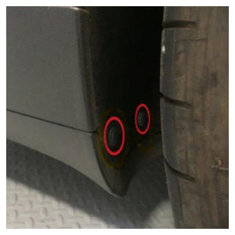
- Install clips securing rocker panel to LH rear wheelhouse liner
NOTE:
2x push clips
 Courtesy of TESLA, INC. Courtesy of TESLA, INC.
|
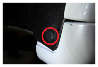
- Install clip securing rocker panel to LH front wheelhouse liner
NOTE:
1x push clip
 Courtesy of TESLA, INC. Courtesy of TESLA, INC.
|
- Position LH scuff plate for installation
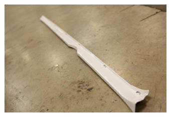 Courtesy of TESLA, INC. Courtesy of TESLA, INC.
|
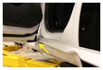 Courtesy of TESLA, INC. Courtesy of TESLA, INC.
|
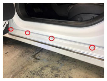
- Install tabs and clips securing LH scuff plate
NOTE:
7x tabs, 7x clips, Secure lower clips and then proceed to install upper tabs
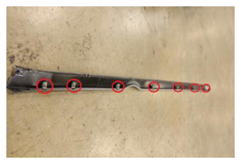 Courtesy of TESLA, INC. Courtesy of TESLA, INC.
|
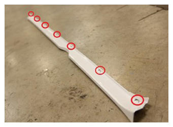 Courtesy of TESLA, INC. Courtesy of TESLA, INC.
|
 Courtesy of TESLA, INC. Courtesy of TESLA, INC.
|
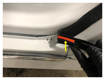
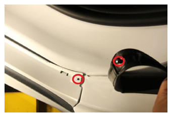
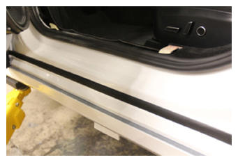
- Install body side secondary seal onto LH rocker panel
NOTE:
1x clip, Apply new double sided adhesive to rear bottom section of secondary seal
 Courtesy of TESLA, INC. Courtesy of TESLA, INC.
|
 Courtesy of TESLA, INC. Courtesy of TESLA, INC.
|
 Courtesy of TESLA, INC. Courtesy of TESLA, INC.
|
- Install RH rocker panel onto vehicle
NOTE:
Secure at front and rear fenders, Be sure to insert rocker above jack pads
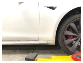 Courtesy of TESLA, INC. Courtesy of TESLA, INC.
|
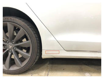 Courtesy of TESLA, INC. Courtesy of TESLA, INC.
|
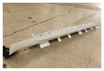 Courtesy of TESLA, INC. Courtesy of TESLA, INC.
|
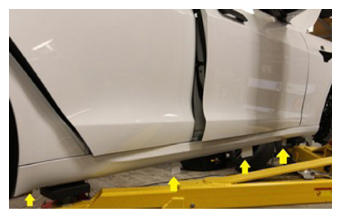
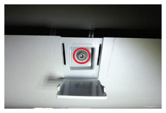
- Install bolts securing RH rocker panel to body
NOTE:
7x upper bolts, 10 mm, 3 N.m, 4x lower bolts, 10 mm, 3 N.m
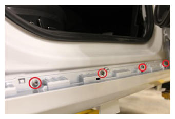 Courtesy of TESLA, INC. Courtesy of TESLA, INC.
|
 Courtesy of TESLA, INC. Courtesy of TESLA, INC.
|
 Courtesy of TESLA, INC. Courtesy of TESLA, INC.
|
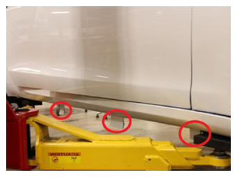
- Secure covers on bottom edge of RH rocker panel
NOTE:
3x covers
 Courtesy of TESLA, INC. Courtesy of TESLA, INC.
|
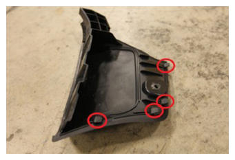
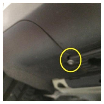
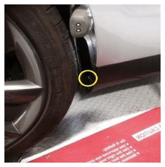
- Install RH rear wheel fairing and secure bolts
NOTE:
2x bolt, 8 mm, 3 N.m, 5x tabs
 Courtesy of TESLA, INC. Courtesy of TESLA, INC.
|
 Courtesy of TESLA, INC. Courtesy of TESLA, INC.
|
 Courtesy of TESLA, INC. Courtesy of TESLA, INC.
|
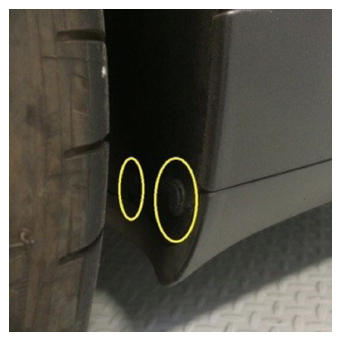
- Install clips securing rocker panel to RH rear wheelhouse liner
NOTE:
2x push clips
 Courtesy of TESLA, INC. Courtesy of TESLA, INC.
|
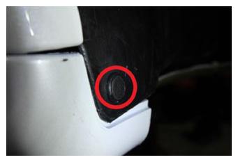
- Install clip securing rocker panel to RH front wheelhouse liner
NOTE:
1x push clip
 Courtesy of TESLA, INC. Courtesy of TESLA, INC.
|
- Position RH scuff plate for installation
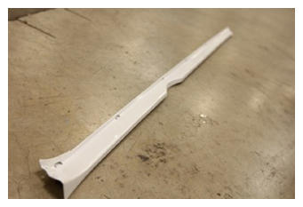 Courtesy of TESLA, INC. Courtesy of TESLA, INC.
|
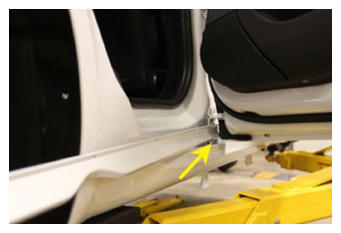 Courtesy of TESLA, INC. Courtesy of TESLA, INC.
|
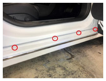
- Install tabs and clips securing RH scuff plate
NOTE:
7x tabs, 7x clips, Secure lower clips and then proceed to install upper tabs
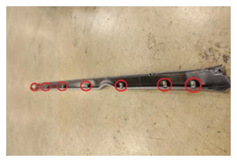 Courtesy of TESLA, INC. Courtesy of TESLA, INC.
|
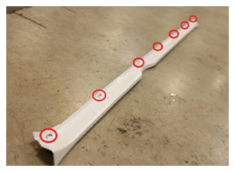 Courtesy of TESLA, INC. Courtesy of TESLA, INC.
|
 Courtesy of TESLA, INC. Courtesy of TESLA, INC.
|
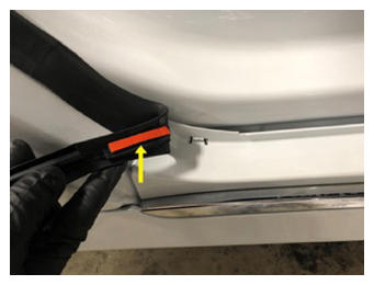
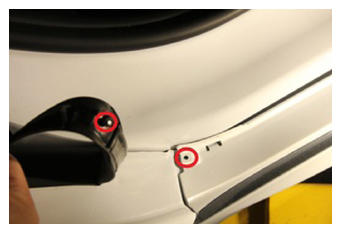
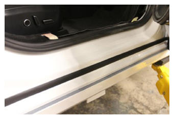
- Install body side secondary seal onto RH rocker panel
NOTE:
1x clip, Apply new double sided adhesive to rear bottom section of secondary seal
 Courtesy of TESLA, INC. Courtesy of TESLA, INC.
|
 Courtesy of TESLA, INC. Courtesy of TESLA, INC.
|
 Courtesy of TESLA, INC. Courtesy of TESLA, INC.
|
- Remove steering wheel holder from vehicle
- Raise all four windows
- Close LH front door
- Verify turn and slip plates are locked
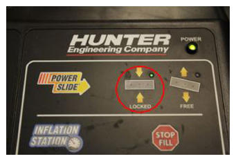 Courtesy of TESLA, INC. Courtesy of TESLA, INC.
|
- Set vehicle ride height to Standard, then drive vehicle onto alignment rack and shift into Park
NOTE:
Recommend assistance for aligning vehicle to ramps
- Latch passenger seat belt to driver buckle
- Exit vehicle and place wheel chocks around driver's rear wheel
- Enter vehicle, enable Jack Mode, shift to neutral, then close driver's door latch
NOTE:
Make sure climate control and headlights are off as well
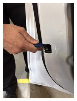 Courtesy of TESLA, INC. Courtesy of TESLA, INC.
|
- Raise 4-post lift and lower onto locks
NOTE:
Set vehicle to comfortable working height, Make sure there's an audible click of the locks on both sides before lowering, otherwise vehicle may tilt to the side
- Torque LH air spring module nut and bolt to LH aft link assembly
NOTE:
1x bolt, 21 mm, 1x nut, 21 mm, 140 N.m
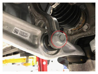 Courtesy of TESLA, INC. Courtesy of TESLA, INC.
|
- Remove existing paint mark from LH air spring module bolt
NOTE:
Clean the area thoroughly so the new marking is not confused with the previous marking
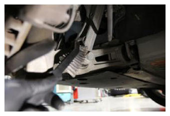 Courtesy of TESLA, INC. Courtesy of TESLA, INC.
|
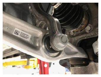
- Mark LH air spring module bolt to show component has been torqued
NOTE:
Use a high visibility paint pen when marking components
 Courtesy of TESLA, INC. Courtesy of TESLA, INC.
|
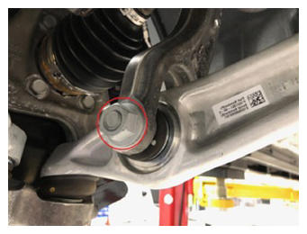
- Torque RH air spring module nut and bolt to RH aft link assembly
NOTE:
1x bolt, 21 mm, 1x nut, 21 mm, 140 N.m
 Courtesy of TESLA, INC. Courtesy of TESLA, INC.
|
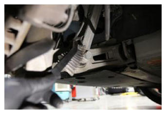
- Remove the existing paint mark from RH air spring module
NOTE:
Clean the area thoroughly so the new marking is not confused with the previous marking
 Courtesy of TESLA, INC. Courtesy of TESLA, INC.
|
- Mark the RH air spring module bolt to show the component has been torqued
NOTE:
Use a high visibility paint pen when marking components
 Courtesy of TESLA, INC. Courtesy of TESLA, INC.
|
- Lower 4-post lift and set onto locks
NOTE:
Set vehicle to comfortable working height, Make sure there's an audible click of the locks on both sides before lowering, otherwise vehicle may tilt to the side
- Set tire machine pressures to match vehicle
NOTE:
Refer to the "Tire and Loading Information" label located on the driver side B-pillar
- Install pressure hoses onto all four wheels so tire pressures can be set automatically
NOTE:
Pull hose from reel and lock into position, then remove valve stem cap and install hose onto valve stem
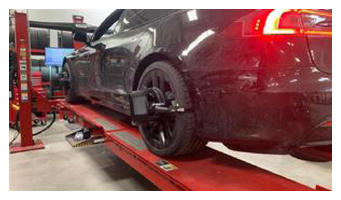
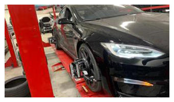
- Install alignment heads onto all four wheels
NOTE:
Position alignment heads near the center of the wheel, Adjust side arms as necessary to grip tires securely
 Courtesy of TESLA, INC. Courtesy of TESLA, INC.
|
 Courtesy of TESLA, INC. Courtesy of TESLA, INC.
|
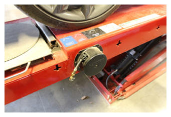
- Remove tire pressure hoses from valve stems
NOTE:
Reinstall valve stem caps
 Courtesy of TESLA, INC. Courtesy of TESLA, INC.
|
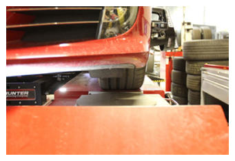
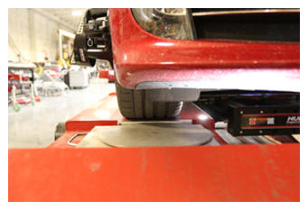
- Check that front turn plates are centered on tires
NOTE:
Adjust turn plate location if necessary
 Courtesy of TESLA, INC. Courtesy of TESLA, INC.
|
 Courtesy of TESLA, INC. Courtesy of TESLA, INC.
|
- Perform rolling compensation
NOTE:
Push vehicle forward using driver's side rear tire, Insert wheel chocks once vehicle has been rolled forward, Turn and slip plates should automatically unlock
- Apply brake pedal depressor
- Perform caster sweep, then center steering wheel per level bubble and lock steering wheel into position
- Print vehicle alignment summary
NOTE:
Include before/after results
- Remove brake pedal depressor, steering wheel level, and steering wheel holder and place vehicle into Park
- Remove alignment heads from all four wheels
- Lower 4-post lift fully
- Use exterior door handle to release driver door latch
- Remove wheel chocks
- Remove vehicle from 4-post lift
NOTE:
Remove suspension from Jack Mode, Release passenger seat belt from driver buckle