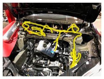
- Place new front trunk harness into the front of the vehicle.
 Courtesy of TESLA, INC. Courtesy of TESLA, INC.
|
- Route cabin portion of front trunk harness through opening in bulkhead and seat sealing grommet.
NOTE:
The sealing grommet is marked for orientation, Ensure the arrow is pointing up.
 Courtesy of TESLA, INC. Courtesy of TESLA, INC.
|
 Courtesy of TESLA, INC. Courtesy of TESLA, INC.
|
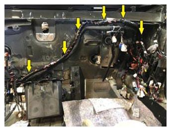
- Remove the plastic cover in the in cabin portion of the Front Harness, then route and secure harness clips to RH side of the Bulkhead.
NOTE:
6x clips.
 Courtesy of TESLA, INC. Courtesy of TESLA, INC.
|
 Courtesy of TESLA, INC. Courtesy of TESLA, INC.
|
- Make connections at the Air Suspension Control Module.
NOTE:
2x connectors.
 Courtesy of TESLA, INC. Courtesy of TESLA, INC.
|
- Secure the Front Harness Ground connection at the In-Cabin Fuse Box.
NOTE:
1x nut, 10 mm, 6 N.m.
 Courtesy of TESLA, INC. Courtesy of TESLA, INC.
|
- Connect the Front Harness connector at the In-Cabin Fuse Box.
NOTE:
1x connector.
 Courtesy of TESLA, INC. Courtesy of TESLA, INC.
|
- Un-bundle RH portion of new front trunk harness and route against bulkhead down RH side behind HV cables that run to the FJB.
 Courtesy of TESLA, INC. Courtesy of TESLA, INC.
|
 Courtesy of TESLA, INC. Courtesy of TESLA, INC.
|
- Raise vehicle partially and lower onto locks.
- Remove the connector carrier for FEM connections from the new harness.
NOTE:
this will aid in creating room for routing the harness up to the RH Body Beam.
 Courtesy of TESLA, INC. Courtesy of TESLA, INC.
|
 Courtesy of TESLA, INC. Courtesy of TESLA, INC.
|
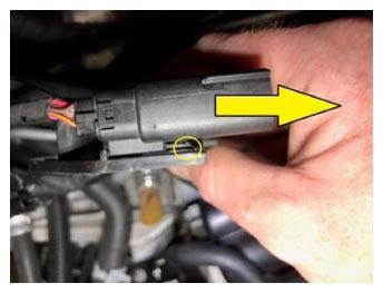
- Apply tape to the secure connector lock for the Fuse Box connector from the RH leg of the harness.
NOTE:
The connector will need to be passed through a tight between the A/C lines and taping the lock in place will assist in the later step.
 Courtesy of TESLA, INC. Courtesy of TESLA, INC.
|
- Route right side of front trunk harness under shock tower cross member and out towards front of RH body beam.
NOTE:
Working from right front fender well, pass the harness through the opening under shock tower cross member, If needed raise or lower the vehicle on the lift to work from above and in the fender well to ease in routing harness.
 Courtesy of TESLA, INC. Courtesy of TESLA, INC.
|
 Courtesy of TESLA, INC. Courtesy of TESLA, INC.
|
- Secure harness clips near Brake Booster.
NOTE:
2x clips.
 Courtesy of TESLA, INC. Courtesy of TESLA, INC.
|
- Secure harness clips at Bulkhead to right of Brake Booster and on body seam in fender well.
NOTE:
2x clips.
 Courtesy of TESLA, INC. Courtesy of TESLA, INC.
|
- Route FJB logic connector down bulkhead along FJB HV cables.
NOTE:
1x connector.
 Courtesy of TESLA, INC. Courtesy of TESLA, INC.
|
 Courtesy of TESLA, INC. Courtesy of TESLA, INC.
|
- Lower vehicle to comfortable working height.
- Route fuse box and ground connectors through opening in A/C lines.
NOTE:
2x connectors.
 Courtesy of TESLA, INC. Courtesy of TESLA, INC.
|
- Secure clips at inner RH shock tower.
NOTE:
1x fir tree clip towards rear of inner shock tower, 1x barrel clip towards the middle.
 Courtesy of TESLA, INC. Courtesy of TESLA, INC.
|
- Route 2 harness legs for steering gear and secure to coolant hose below.
NOTE:
2x clips, These legs of the harness sit on top and are secured to the coolant lines with large circle clips on the bottom.
 Courtesy of TESLA, INC. Courtesy of TESLA, INC.
|
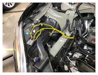
- Route leg of harness with connectors for headlamp, coolant 3 way valve, fan controller, and wheel speed sensor to RH outer side of RH body beam.
NOTE:
4x connectors, Coolant 3 way valve and RH fan controller connectors are routed down to the underside of vehicle while the others remain above body beam for installation.
 Courtesy of TESLA, INC. Courtesy of TESLA, INC.
|
 Courtesy of TESLA, INC. Courtesy of TESLA, INC.
|
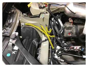
- Locate the RH harness ground connections from the separate harness legs and route towards grounding points on RH Shock Tower.
NOTE:
3x cables.
 Courtesy of TESLA, INC. Courtesy of TESLA, INC.
|
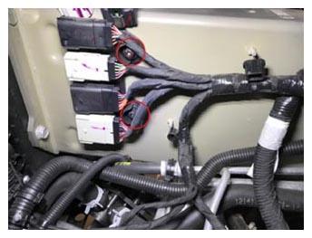
- Install the Front Harness FEM connectors to the harness connector carrier.
NOTE:
4x connectors, See Image for Connector orientation to carrier.
 Courtesy of TESLA, INC. Courtesy of TESLA, INC.
|
- Install the FEM Connector Carrier to the RH Body Beam.
NOTE:
2x nuts, 10 mm, plastic, 3 N.m.
 Courtesy of TESLA, INC. Courtesy of TESLA, INC.
|
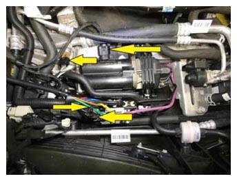
- Route harness and connect the air suspension compressor, valve block, and low side A/C pressure sensor.
NOTE:
3x connectors, 1x line clip, Take care not to mix up the 2 air suspension connectors, Power supply is a slightly larger 2 wire connector and is connected near the subframe while the logic connector is directly at the air compressor.
 Courtesy of TESLA, INC. Courtesy of TESLA, INC.
|
- Connect front Fascia and FEM connectors to Front Harness at connector carrier on RH Body Beam.
NOTE:
4x connectors.
 Courtesy of TESLA, INC. Courtesy of TESLA, INC.
|
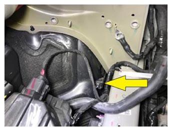
- Connect RH front wheel speed sensor.
NOTE:
1x connector.
 Courtesy of TESLA, INC. Courtesy of TESLA, INC.
|
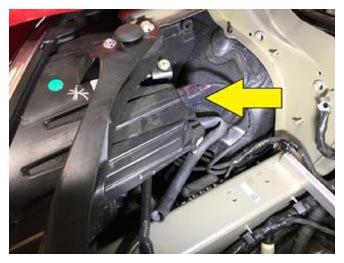
- Connect RH headlamp.
NOTE:
1x connector.
 Courtesy of TESLA, INC. Courtesy of TESLA, INC.
|
- Make RH harness leg connections at the Steering Gear.
NOTE:
3x connectors, Ensure connector locking tabs are engaged after making connections.
 Courtesy of TESLA, INC. Courtesy of TESLA, INC.
|
- Secure front harness clips to RH body beam.
NOTE:
4x barrel clips.
 Courtesy of TESLA, INC. Courtesy of TESLA, INC.
|
- Install the 3 ground fasteners at the RH Shock Tower.
NOTE:
3x bolts, 13 mm, 15 N.m, 1x edge clip.
- Connect A/C lines by RH shock tower.
NOTE:
2x bolts, 10 mm, 8 N.m, Install new O-rings prior to connecting lines.
 Courtesy of TESLA, INC. Courtesy of TESLA, INC.
|
- Secure A/C line bracket to shock tower cross member.
NOTE:
1x nut, 10 mm, 6 N.m.
 Courtesy of TESLA, INC. Courtesy of TESLA, INC.
|
- Secure A/C line to RH side of A/C compressor.
NOTE:
1x nut, 10 mm, 10 N.m, Install new O-ring prior to connecting lines.
 Courtesy of TESLA, INC. Courtesy of TESLA, INC.
|
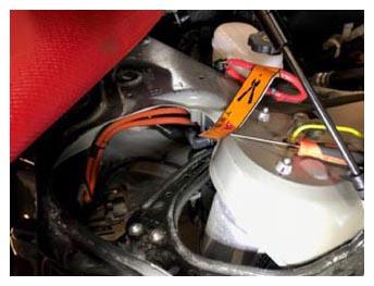
- Route harness leg to ride height sensor and FRL and make connections.
NOTE:
1x connector, 2x edge clips, Connect RH ride height sensor, harness edge clip, and secure FRL edge clip, The new harness should come with a new FRL attached, remove and discard the old FRL.
 Courtesy of TESLA, INC. Courtesy of TESLA, INC.
|
 Courtesy of TESLA, INC. Courtesy of TESLA, INC.
|
- Route the harness leg and make connections at the Brake Booster, Fluid Reservoir, and Master Cylinder.
NOTE:
3x connectors, 1x edge clip.
- Route harness leg and make ground connection at the AC compressor.
NOTE:
1x bolt, T25, 7 N.m.
 Courtesy of TESLA, INC. Courtesy of TESLA, INC.
|
 Courtesy of TESLA, INC. Courtesy of TESLA, INC.
|
- Secure main section of front trunk harness to RH side of bulkhead.
NOTE:
1x clip, 2x nuts, 10 mm, 5 N.m.
 Courtesy of TESLA, INC. Courtesy of TESLA, INC.
|
- Re-position coolant bottle and install the fasteners securing the coolant bottle to the shock tower cross member.
NOTE:
4x bolts, 10 mm, 6 N.m.
 Courtesy of TESLA, INC. Courtesy of TESLA, INC.
|
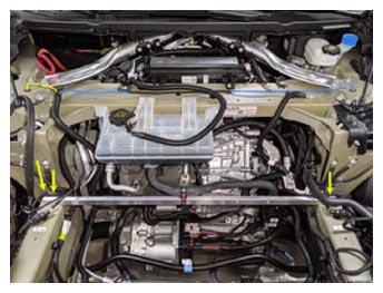
- Install 12V battery beam.
NOTE:
2x bolts, T30, 3.5 N.m, 1x edge clip.
 Courtesy of TESLA, INC. Courtesy of TESLA, INC.
|
- Install the harness edge clip to the Battery Beam at RH end.
NOTE:
1x clip.
 Courtesy of TESLA, INC. Courtesy of TESLA, INC.
|
- Secure coolant reservoir hose to 12V battery beam.
NOTE:
1x bolt, T30, 5 N.m.
 Courtesy of TESLA, INC. Courtesy of TESLA, INC.
|
- Place 12V battery with bracket onto the battery beam and shock tower cross member for installation.
NOTE:
The 12V positive cable to the E-fuse module is still connected to the battery and can be placed for installation together.
- Install fasteners securing battery bracket to battery beam and shock tower cross member.
NOTE:
2x bolts, T30, 5 N.m, 2x bolts, 13 mm, 15 N.m.
 Courtesy of TESLA, INC. Courtesy of TESLA, INC.
|
- Secure 12V power supply cable to E-fuse assembly.
NOTE:
1x patch bolt, T30, 7 N.m, Use new bolt.
 Courtesy of TESLA, INC. Courtesy of TESLA, INC.
|
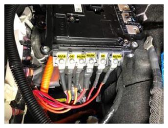
- Install screws securing small cables to side of E-fuse assembly.
NOTE:
6x screws, PH2, 4 N.m, Make sure to install wires in proper positions as noted during removal.
 Courtesy of TESLA, INC. Courtesy of TESLA, INC.
|
- Connect logic connector to E-fuse assembly.
NOTE:
1x connector, Secure red locking tab.
 Courtesy of TESLA, INC. Courtesy of TESLA, INC.
|
- Install screw securing small cable to front of E-fuse assembly.
NOTE:
1x screw, PH2, 5 N.m, Make sure to install wire in proper position as noted during removal (H).
 Courtesy of TESLA, INC. Courtesy of TESLA, INC.
|
- Install bolts securing large cables to front of E-fuse assembly.
NOTE:
2x patch bolts, T30, 5 N.m, Make sure to install wires in proper positions as noted during removal, Install new patch bolts (G, J).
 Courtesy of TESLA, INC. Courtesy of TESLA, INC.
|
- Install cover onto RH side of E-fuse assembly.
NOTE:
Align cover with cable cutouts and fully engage until audible click is heard, Image on left shows where to align cover with cables.
 Courtesy of TESLA, INC. Courtesy of TESLA, INC.
|
 Courtesy of TESLA, INC. Courtesy of TESLA, INC.
|
- Install bolts securing E-fuse cover onto E-fuse assembly.
NOTE:
3x screws, T25, 2.7 N.m.
 Courtesy of TESLA, INC. Courtesy of TESLA, INC.
|
- Position E-fuse onto bracket.
NOTE:
2x tabs, Route the 12V+ cable from E-fuse down to DCDC for installation.
 Courtesy of TESLA, INC. Courtesy of TESLA, INC.
|
 Courtesy of TESLA, INC. Courtesy of TESLA, INC.
|
- Install nut securing E-fuse assembly to electrical battery heater bracket.
NOTE:
1x nut, 10 mm, 7 N.m.
 Courtesy of TESLA, INC. Courtesy of TESLA, INC.
|
- Route leg of harness for connections to electric battery heater, DCDC, and E-fuse ground down behind the bulkhead for installation.
NOTE:
3x connectors, To be secured from underneath the vehicle later on.
 Courtesy of TESLA, INC. Courtesy of TESLA, INC.
|
- Connect TXV.
NOTE:
1x connector.
 Courtesy of TESLA, INC. Courtesy of TESLA, INC.
|
- Secure harness clip to RH side of sealing grommet at Bulkhead.
NOTE:
1x barrel clip.
 Courtesy of TESLA, INC. Courtesy of TESLA, INC.
|
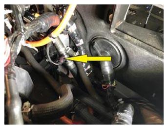
- Connect coolant temp sensor to LH side of electrical battery heater.
NOTE:
1x connector.
 Courtesy of TESLA, INC. Courtesy of TESLA, INC.
|
- Un-bundle the LH portion of the Front Harness and feed under LH side of the Shock Tower Cross Member and along the LH Body Beam.
NOTE:
Starting from the Bulkhead with the largest connector which is for the ABS control unit, route the harness under the coolant lines then along the inner side of the LH Shock Tower under the Shock Tower Support Cross Member then down the LH Body Beam, Be sure to route harness behind brake lines below Battery Beam, The connector for the ABS Control unit is the largest, recommend passing this connector through the opening between the brake lines and LH Body Beam first while routing harness, then continuing with the more forward sections of the harness until the harness fir tree clips can be seen near their locating holes under the Shock Tower Cross Member.
 Courtesy of TESLA, INC. Courtesy of TESLA, INC.
|
 Courtesy of TESLA, INC. Courtesy of TESLA, INC.
|
 Courtesy of TESLA, INC. Courtesy of TESLA, INC.
|
 Courtesy of TESLA, INC. Courtesy of TESLA, INC.
|
 Courtesy of TESLA, INC. Courtesy of TESLA, INC.
|
- Secure main LH section of front trunk harness to body below 2 coolant lines to the left of sealing grommet.
NOTE:
1x barrel clip, Body stud where harness clip secures is NOT on bulkhead, it is on the rear section of the body beam and points straight up.
 Courtesy of TESLA, INC. Courtesy of TESLA, INC.
|
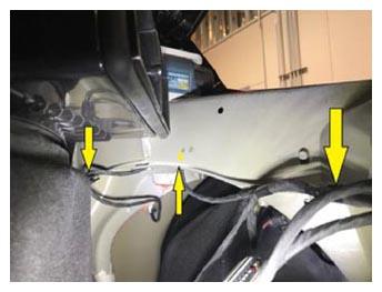
- Route leg of harness for LH side repeater and ride height sensor behind LH wheelhouse liner.
NOTE:
3x edge clips.
 Courtesy of TESLA, INC. Courtesy of TESLA, INC.
|
- Secure connections to LH Side Repeater.
NOTE:
2x connectors.
 Courtesy of TESLA, INC. Courtesy of TESLA, INC.
|
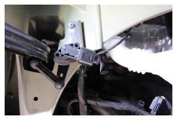
- Connect LH front ride height sensor.
NOTE:
1x connector.
 Courtesy of TESLA, INC. Courtesy of TESLA, INC.
|
 Courtesy of TESLA, INC. Courtesy of TESLA, INC.
|
- Connect coolant temp sensor near LH front wheelhouse liner and bulkhead.
NOTE:
1x connector.
 Courtesy of TESLA, INC. Courtesy of TESLA, INC.
|
- Dual Motor Vehicles Only:
Connect front drive unit logic connector.
NOTE:
1x connector.
 Courtesy of TESLA, INC. Courtesy of TESLA, INC.
|
- Connect PT coolant pump 1.
 Courtesy of TESLA, INC. Courtesy of TESLA, INC.
|
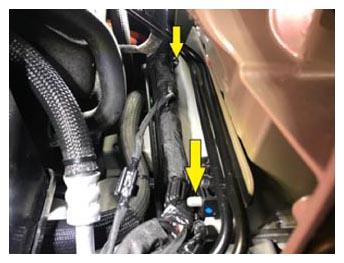
- Secure front harness clips at LH inner shock tower.
NOTE:
2x fir tree clips.
 Courtesy of TESLA, INC. Courtesy of TESLA, INC.
|
- Route and secure harness leg for coolant 4 way valve below battery beam and connect.
NOTE:
1x connector, 1x fir tree clip, 2x line clips.
 Courtesy of TESLA, INC. Courtesy of TESLA, INC.
|
 Courtesy of TESLA, INC. Courtesy of TESLA, INC.
|
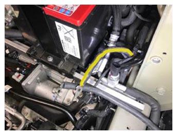
- Route and secure the harness ground at the LH Shock Tower.
NOTE:
1x bolt, 13 mm, 15 N.m.
 Courtesy of TESLA, INC. Courtesy of TESLA, INC.
|
 Courtesy of TESLA, INC. Courtesy of TESLA, INC.
|
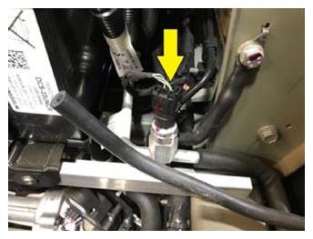
- Connect high side A/C pressure/temp sensor.
NOTE:
1x connector.
 Courtesy of TESLA, INC. Courtesy of TESLA, INC.
|
- Secure brake line brackets on LH body beam.
NOTE:
3x brackets, Rotate brackets into position and gently press brake lines into guide channels.
 Courtesy of TESLA, INC. Courtesy of TESLA, INC.
|
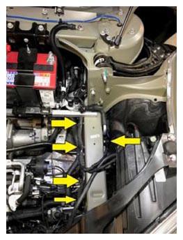
- Secure harness clips at LH body beam.
 Courtesy of TESLA, INC. Courtesy of TESLA, INC.
|
- Route harness leg for LH fan controller on outside of LH body beam.
 Courtesy of TESLA, INC. Courtesy of TESLA, INC.
|
- Connect LH front wheel speed sensor.
NOTE:
1x connector.
 Courtesy of TESLA, INC. Courtesy of TESLA, INC.
|
- Connect LH headlamp.
NOTE:
1x connector.
 Courtesy of TESLA, INC. Courtesy of TESLA, INC.
|
- Route harness leg near ABS pump and make connection to battery coolant pump 2.
NOTE:
1x connector, 1x line clip.
 Courtesy of TESLA, INC. Courtesy of TESLA, INC.
|
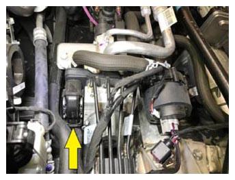
- Connect ABS module connector.
NOTE:
1x connector, Engage connector and flip latch to fully engage and lock connection.
 Courtesy of TESLA, INC. Courtesy of TESLA, INC.
|
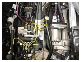
- Route and secure harness leg for steering gear, air compressor, heat exchanger, and RKE antenna.
NOTE:
1x line clip, 1x square fir tree clip, 1x fir tree clip.
 Courtesy of TESLA, INC. Courtesy of TESLA, INC.
|
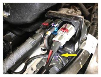
- Connect Steering Gear.
NOTE:
1x connector, Be sure to engage grey locking tab after making connection.
 Courtesy of TESLA, INC. Courtesy of TESLA, INC.
|
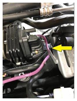
- Connect air suspension compressor.
NOTE:
1x connector.
 Courtesy of TESLA, INC. Courtesy of TESLA, INC.
|
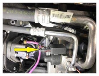
- Connect battery chiller and EXV.
NOTE:
1x connector, Be sure to engage red locking tab after making connection.
 Courtesy of TESLA, INC. Courtesy of TESLA, INC.
|
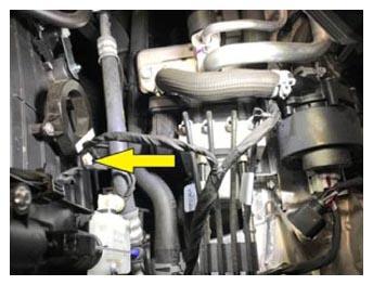
- Connect RKE antenna.
NOTE:
1x connector.
 Courtesy of TESLA, INC. Courtesy of TESLA, INC.
|
- Raise vehicle to comfortable working height.
- Route and secure the E-fuse harness ground at the bottom of the E-fuse Assembly.
NOTE:
1x bolt, T25, 4 N.m, Install new patch bolt.
 Courtesy of TESLA, INC. Courtesy of TESLA, INC.
|
- Connect lower battery coolant heater connection and secure to bracket.
NOTE:
1x connector, 1x clip.
 Courtesy of TESLA, INC. Courtesy of TESLA, INC.
|
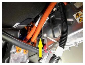
- Connect DCDC logic connector.
NOTE:
1x connector.
 Courtesy of TESLA, INC. Courtesy of TESLA, INC.
|
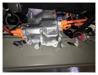
- Route and install 12V positive terminal to DCDC.
NOTE:
1x bolt, 13 mm, 13 N.m.
 Courtesy of TESLA, INC. Courtesy of TESLA, INC.
|
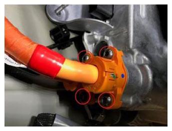
- Install HV cables to FJB.
NOTE:
4x bolts, T30, 7 N.m.
 Courtesy of TESLA, INC. Courtesy of TESLA, INC.
|
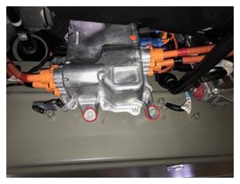
- Install fasteners securing FJB to bulkhead.
NOTE:
2x bolts, 10 mm, 7 N.m, 1x nut, 10 mm, 9 N.m.
 Courtesy of TESLA, INC. Courtesy of TESLA, INC.
|
 Courtesy of TESLA, INC. Courtesy of TESLA, INC.
|
- Secure FJB HV harness clip at bulkhead.
NOTE:
1x clip.
 Courtesy of TESLA, INC. Courtesy of TESLA, INC.
|
- Connect FJB logic connector.
NOTE:
1x connector.
 Courtesy of TESLA, INC. Courtesy of TESLA, INC.
|
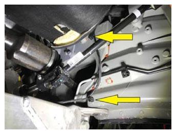
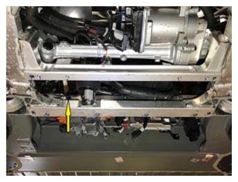
- Secure harness for battery coolant pump 1 connector.
NOTE:
2x barrel clips, 1x fir tree clip.
 Courtesy of TESLA, INC. Courtesy of TESLA, INC.
|
 Courtesy of TESLA, INC. Courtesy of TESLA, INC.
|
- Connect battery coolant pump 1.
NOTE:
1x connector.
 Courtesy of TESLA, INC. Courtesy of TESLA, INC.
|
- Install the bolts securing the Bash Plate Stamping and Skid Plate to the front Subframe.
NOTE:
2x bolts, 10 mm, 9 N.m.
 Courtesy of TESLA, INC. Courtesy of TESLA, INC.
|
- Connect LH fan control module and secure harness.
NOTE:
1x connector, 1x clip.
 Courtesy of TESLA, INC. Courtesy of TESLA, INC.
|
- Connect RH fan control module and secure harness.
NOTE:
1x connector, 1x clip.
 Courtesy of TESLA, INC. Courtesy of TESLA, INC.
|
- Connect coolant 3 way valve.
NOTE:
1x connector.
 Courtesy of TESLA, INC. Courtesy of TESLA, INC.
|
- Install front aero shield into position and hand tighten center bolts.
NOTE:
2x bolts, 10 mm, 3 N.m, Make sure the front of the aero shield is inserted into tabs on fascia.
 Courtesy of TESLA, INC. Courtesy of TESLA, INC.
|
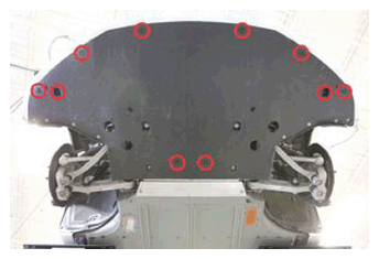
- Install clips securing front aero shield to vehicle.
NOTE:
10x push clips.
 Courtesy of TESLA, INC. Courtesy of TESLA, INC.
|
- Install and tighten bolts securing front aero shield to vehicle.
NOTE:
12x bolts, 10 mm, 3 N.m.
 Courtesy of TESLA, INC. Courtesy of TESLA, INC.
|
- Lower vehicle to comfortable working height.
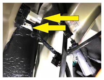
- Connect RH side repeater.
NOTE:
2x connectors.
 Courtesy of TESLA, INC. Courtesy of TESLA, INC.
|
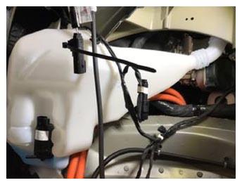
- Place washer bottle for installation.
 Courtesy of TESLA, INC. Courtesy of TESLA, INC.
|
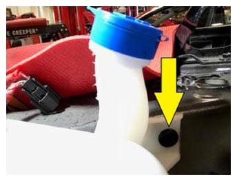
- Install fasteners securing washer bottle to body.
NOTE:
1x bolts, 10 mm, 5 N.m, 2x nuts, 10 mm, 5 N.m, 1x clip.
 Courtesy of TESLA, INC. Courtesy of TESLA, INC.
|
 Courtesy of TESLA, INC. Courtesy of TESLA, INC.
|
 Courtesy of TESLA, INC. Courtesy of TESLA, INC.
|
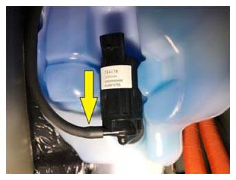
- Secure washer fluid line to pump.
NOTE:
1x hose.
 Courtesy of TESLA, INC. Courtesy of TESLA, INC.
|
- Secure harness clips to washer bottle.
NOTE:
2x edge clips.
 Courtesy of TESLA, INC. Courtesy of TESLA, INC.
|
- Connect washer fluid pump.
NOTE:
1x connector.
 Courtesy of TESLA, INC. Courtesy of TESLA, INC.
|
- Connect washer fluid level sensor.
NOTE:
1x connector.
 Courtesy of TESLA, INC. Courtesy of TESLA, INC.
|
- Connect front trunk harness to hood harness.
NOTE:
1x connector.
 Courtesy of TESLA, INC. Courtesy of TESLA, INC.
|
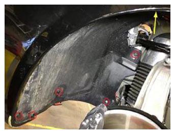
- Secure rear portion of RH front wheelhouse liner to vehicle.
NOTE:
1x nut, 10 mm, 4 N.m, 5x push clips.
 Courtesy of TESLA, INC. Courtesy of TESLA, INC.
|
- Install RH front wheel.
NOTE:
5x nuts, 21 mm, 175 N.m.
 Courtesy of TESLA, INC. Courtesy of TESLA, INC.
|
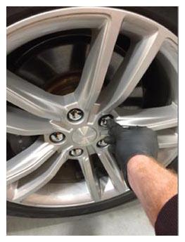
- Lower vehicle until tires are touching the ground.
- Torque the RH Lug Nuts to specification.
NOTE:
5x lug nuts, 21 mm, 175 N.m. Wheel lugs should always be torqued in a star pattern and then double checked after all 5 lug nuts have been torqued. Install lug nut covers if equipped.
 Courtesy of TESLA, INC. Courtesy of TESLA, INC.
|
 Courtesy of TESLA, INC. Courtesy of TESLA, INC.
|
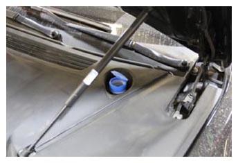
- Top off windshield washer fluid.
 Courtesy of TESLA, INC. Courtesy of TESLA, INC.
|
- Connect PTC heater HV Cable at FJB.
NOTE:
1x connector.
 Courtesy of TESLA, INC. Courtesy of TESLA, INC.
|
- Install 12V cable cover to E-fuse assembly and secure.
NOTE:
1x patch bolt, T30, 3.5 N.m, Use new bolt.
 Courtesy of TESLA, INC. Courtesy of TESLA, INC.
|
- Place air suspension reservoir into position.
 Courtesy of TESLA, INC. Courtesy of TESLA, INC.
|
- Loosely install air suspension reservoir brackets.
NOTE:
2x screws, T25, 2.5 N.m.
 Courtesy of TESLA, INC. Courtesy of TESLA, INC.
|
- Install wiper motor.
NOTE:
3x bolts, 10 mm, 6 N.m, 1x connector.
 Courtesy of TESLA, INC. Courtesy of TESLA, INC.
|
 Courtesy of TESLA, INC. Courtesy of TESLA, INC.
|
- Secure air suspension reservoir brackets.
NOTE:
2x screws, T25, 2.5 N.m.
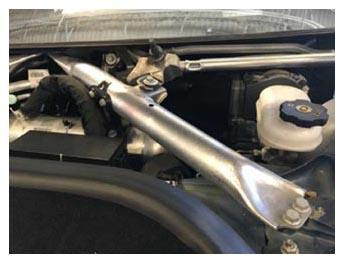
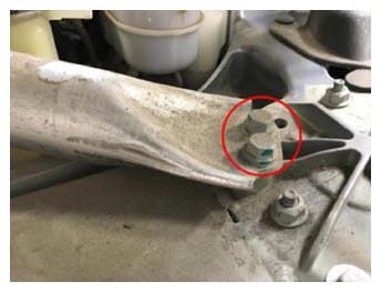
- Install LH shock tower brace.
NOTE:
1x bolt, 13 mm, 30 N.m, 2x bolts, 13 mm, 20 N.m.
 Courtesy of TESLA, INC. Courtesy of TESLA, INC.
|
 Courtesy of TESLA, INC. Courtesy of TESLA, INC.
|
 Courtesy of TESLA, INC. Courtesy of TESLA, INC.
|
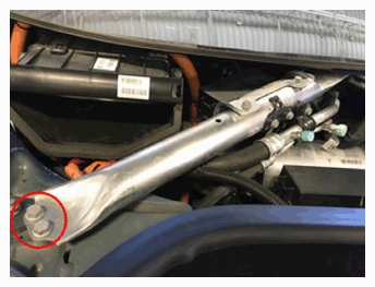
- Install RH shock tower brace.
NOTE:
2x bolts, 13 mm, 20 N.m, 1x bolt, 13 mm, 30 N.m.
 Courtesy of TESLA, INC. Courtesy of TESLA, INC.
|
 Courtesy of TESLA, INC. Courtesy of TESLA, INC.
|
- Place fuse box into vehicle and reconnect harness connectors.
NOTE:
3x connectors.
 Courtesy of TESLA, INC. Courtesy of TESLA, INC.
|
- Position fuse box onto body.
NOTE:
2x tabs.
 Courtesy of TESLA, INC. Courtesy of TESLA, INC.
|
- Install new nut securing 12V supply cable to DCDC.
NOTE:
1x nyloc nut, 13 mm, 12 N.m, Install new nyloc nut.
 Courtesy of TESLA, INC. Courtesy of TESLA, INC.
|
- Install bolts securing fuse box to body.
NOTE:
2x bolts, 10 mm, 6 N.m.
 Courtesy of TESLA, INC. Courtesy of TESLA, INC.
|
- Reconnect pyrotechnic fuse connector.
NOTE:
1x connector, Be sure to secure locking clip.
 Courtesy of TESLA, INC. Courtesy of TESLA, INC.
|
- Secure clips holding 12V battery supply cable to fuse box and strut tower beam.
NOTE:
3x clips.
 Courtesy of TESLA, INC. Courtesy of TESLA, INC.
|
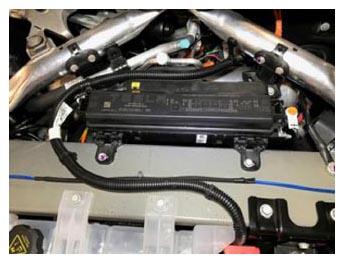
- Reinstall fuse box cover.
NOTE:
2x clips.
 Courtesy of TESLA, INC. Courtesy of TESLA, INC.
|
- Secure front trunk harness ground at shock tower cross member.
NOTE:
1x bolt, 13 mm, 15 N.m.
 Courtesy of TESLA, INC. Courtesy of TESLA, INC.
|
- Secure front trunk harness ground to 12V negative terminal clamp.
NOTE:
1x edge clip, 1x nyloc nut, 10 mm, 5 N.m, Install new nut.
 Courtesy of TESLA, INC. Courtesy of TESLA, INC.
|
- Install underhood storage unit.
NOTE:
Install harness and grommet.
 Courtesy of TESLA, INC. Courtesy of TESLA, INC.
|
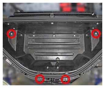
- Install bolts and clips securing underhood storage unit.
NOTE:
2x bolts, 10 mm, 7 N.m, 2x push clips.
 Courtesy of TESLA, INC. Courtesy of TESLA, INC.
|
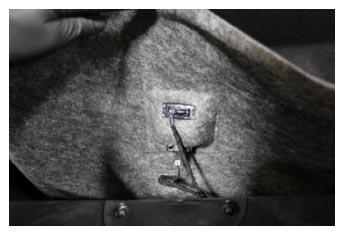
- Install underhood storage carpet and reconnect light and release switch connectors.
NOTE:
2x connectors, Secure edges of carpet underneath underhood storage unit seal.
 Courtesy of TESLA, INC. Courtesy of TESLA, INC.
|