Removal and Installation
Camshaft: Removal and Installation
NOTE:
This section describes removal/installation procedure of camshaft without removing front cover. If front cover is removed or installed, refer to [Rocker Cover: Removal and Installation] Removal and Installation.
Removal
1) Remove the rocker cover. Refer to Removal and Installation.
2) Remove the drive belt. Refer to [Drive Belts: Removal and Installation] Removal and Installation.
3) Disconnect and remove the camshaft position sensor (PHASE).
4) Disconnect the IVT control solenoid electrical connector.
5) Disconnect the ground electrical connections from the front cover.
6) Remove IVT control cover bolts in the order as shown.
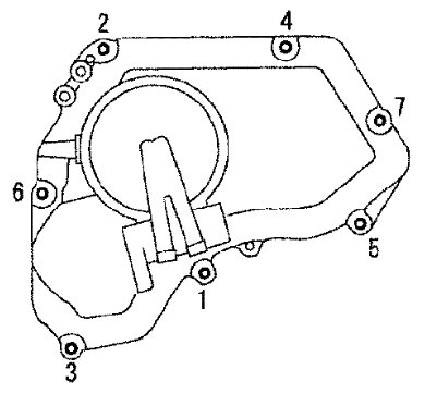
7) Remove the IVT control cover by cutting the sealant using Tool.

8) Set the No.1 cylinder at TDC on its compression stroke as follows:
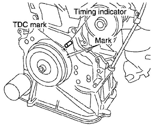
a) Rotate crankshaft pulley clockwise, and align mating marks for TDC with timing indicator on front cover, as shown.
b) Make sure that the mating marks on camshaft sprockets are lined up with the yellow links in the timing chain, as shown.
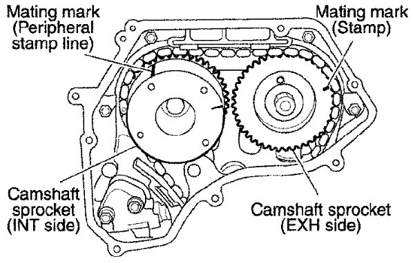
- If not, rotate crankshaft pulley one more turn to line up the mating marks to the yellow links, as shown.
9) Pull the timing chain guide out between the camshaft sprockets through front cover.
10) Line up the mating marks on camshaft sprockets with the yellow links in the timing chain, and paint an indelible mating mark on the sprocket and timing chain link plate.
CAUTION:
Do not rotate the crankshaft or camshaft while the timing chain is removed. It causes interference between valve and piston.
NOTE:
Maintaining chain tension is not necessary. Crankshaft sprocket and timing chain do not disconnect structurally while front cover is attached.
11) Push in the tensioner plunger and hold. Insert a stopper pin into the hole on tensioner body to hold the chain tensioner. Remove the timing chain tensioner.
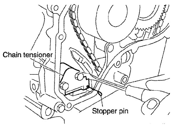
- Use a wire with 0.5 mm (0.02 in) diameter for a stopper pin.
12) Secure the camshaft using a suitable tool as shown. Loosen the camshaft sprocket bolts and remove the camshaft sprockets.
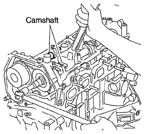
13) Loosen the camshaft bracket bolts in the order as shown, and remove the camshaft brackets and camshafts.
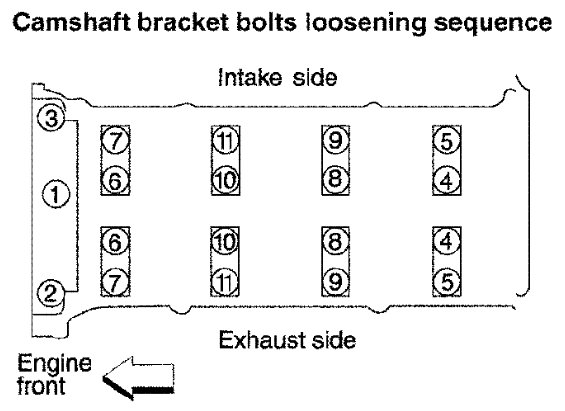
- Remove No.1 camshaft bracket by slightly tapping it with a rubber mallet.
- Note positions, and set them aside in the order removed.
14) Remove the valve lifters.
- Note positions, and set them aside in the order removed.
Inspection after Removal
Camshaft Runout
1) Put V-block on a precise flat table, and support No. 2 and 5 journals of camshaft.
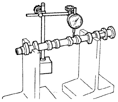
CAUTION:
Do not support No. 1 journal (on the side of camshaft sprocket) because it has a different diameter from the other four locations.
2) Set a dial indicator vertically to No. 3 journal.
3) Turn camshaft to one direction with hands, and measure the camshaft runout on the dial indicator. (Total indicator reading)

4) If out of the standard, replace camshaft.
Camshaft Cam Height
5) Measure the camshaft cam height with a micrometer.
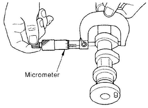
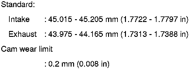
6) If wear is beyond the limit, replace camshaft.
Camshaft Journal Oil Clearance
CAMSHAFT JOURNAL DIAMETER
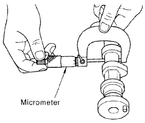
Measure the outer diameter of camshaft journal with a micrometer.

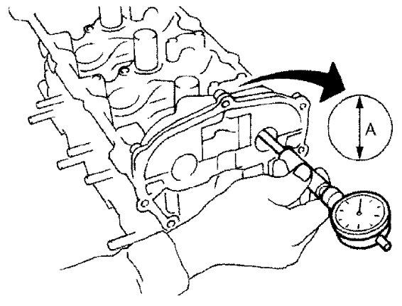
CAMSHAFT BRACKET INNER DIAMETER
- Tighten camshaft bracket bolts with the specified torque. Refer to [Camshaft: Removal and Installation].
- Measure inner diameter "A" of camshaft bracket with a bore gauge.

CAMSHAFT JOURNAL OIL CLEARANCE
- (Oil clearance) = (Camshaft bracket inner diameter) - (Camshaft journal diameter)

- If out of the standard, replace either or both camshaft and cylinder head.
NOTE:
Camshaft brackets cannot be replaced as single parts, because they are machined together with cylinder head. Replace whole cylinder head assembly.
Camshaft End Play
7) Install camshaft in cylinder head. Refer to [Camshaft: Removal and Installation].
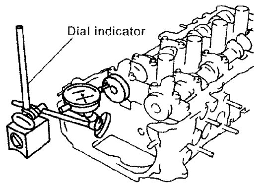
8) Install a dial indicator in thrust direction on front end of camshaft. Measure the camshaft end play on the dial indicator when camshaft is moved forward/backward (in direction to axis).

- Measure the following parts if out of the standard.
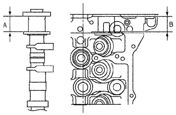
- Dimension "A" for camshaft No. 1 journal

- Dimension "B" for cylinder head No. 1 journal bearing

- Use the standards above, and then replace camshaft and/or cylinder head, if necessary.
Camshaft Sprocket Runout
9) Put V-block on precise flat table, and support No. 2 and 5 journals of camshaft.
CAUTION:
Do not support No. 1 journal (on the side of camshaft sprocket) because it has a different diameter from the other four locations.
10) Measure the camshaft sprocket runout with a dial indicator. (Total indicator reading)
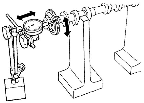

- If it exceeds the limit, replace camshaft sprocket.
Valve Lifter
Check if surface of valve lifter has any wear or cracks.
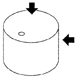
- If anything above is found, replace valve lifter. Refer to [Service Data and Specifications] [1][2]Specifications.
Valve Lifter Clearance
VALVE LIFTER OUTER DIAMETER
- Measure the outer diameter of valve lifter with a micrometer.
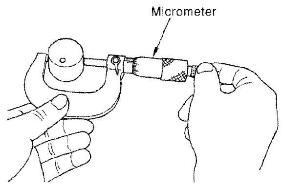

VALVE LIFTER HOLE DIAMETER
Measure the diameter of valve lifter hole of cylinder head with an inside micrometer.
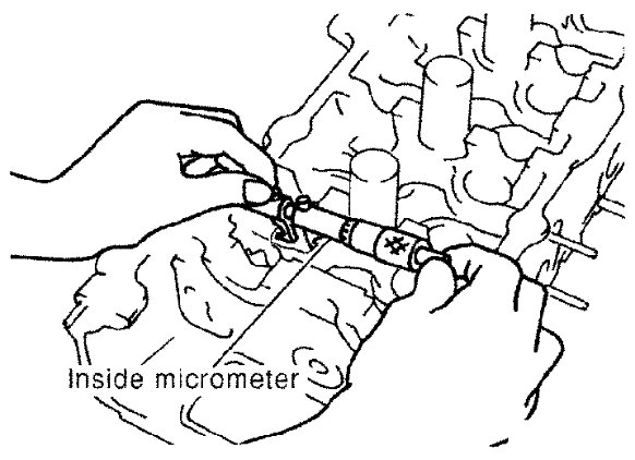

VALVE LIFTER CLEARANCE
- (Valve lifter clearance) = (Valve lifter hole diameter) - (Valve lifter outer diameter)

- If out of the standard, referring to the standard of valve lifter outer diameter and valve lifter hole diameter, replace either or both valve lifter and cylinder head.
Installation
1) Install valve lifters.
- Install them in the original positions.
2) Install camshafts.
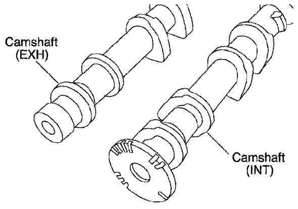
- Distinction between intake and exhaust camshafts is performed with the different shapes of rear end.

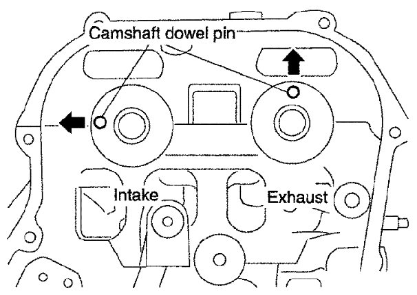
- Install camshafts so that camshaft dowel pins on the front side are positioned as shown.
3) Install camshaft brackets with the following procedure:
a) Remove foreign material completely from camshaft bracket backside and from cylinder head installation face.
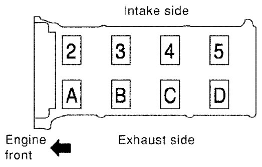
b) Install camshaft brackets (No. 2 to 5) aligning the identification marks on upper surface as shown.
NOTE:
Install so that identification mark can be correctly read when viewed from the exhaust side.
c) Install camshaft bracket (No. 1) with the following procedure:
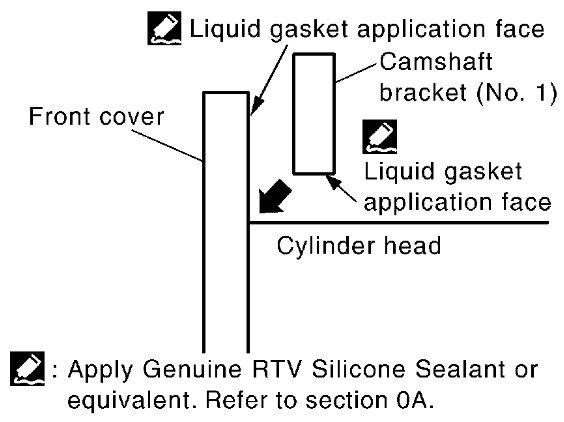
i) Apply liquid gasket to camshaft bracket (No. 1) as shown.
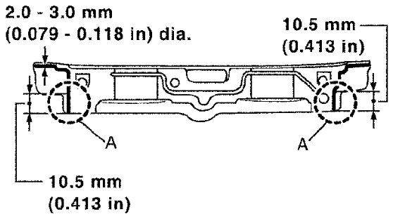
Use Genuine RTV Silicone Sealant or equivalent. Refer to [Recommended Chemical Products and Sealants] Recommended Chemical Products and Sealants.
CAUTION:
After installation, be sure to wipe off any excessive liquid gasket leaking from part (A).
ii) Apply liquid gasket to camshaft bracket (No. 1) contact surface on the front cover backside.
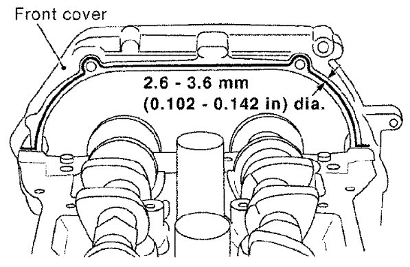
Use Genuine RTV Silicone Sealant or equivalent. Refer to [Recommended Chemical Products and Sealants] Recommended Chemical Products and Sealants.
- Apply liquid gasket to the outside of bolt hole on front cover.
iii) Locate camshaft bracket (No. 1) near installation position, and install it without disturbing the liquid gasket applied to the surfaces.
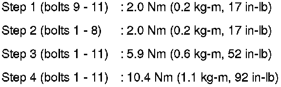
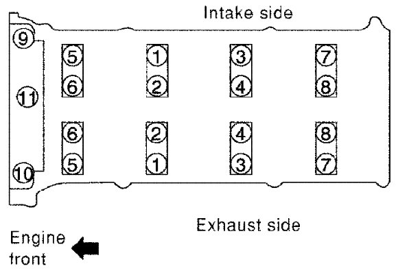
4) Tighten bolts of camshaft brackets in the following steps, in numerical order as shown.
CAUTION:
After tightening bolts of camshaft brackets, be sure to wipe off excessive liquid gasket from the parts.
5) Install camshaft position sensor (PHASE).
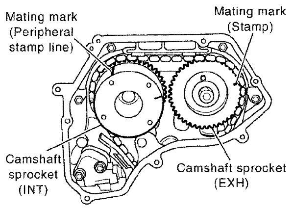
6) Install camshaft sprockets.
- Install them by aligning the mating marks on each camshaft sprocket with the paint marks on the timing chain link plates during removal.
CAUTION:
- Aligned mating marks could slip. Therefore, after matching them, hold the timing chain in place by hand.
- Before and after installing chain tensioner, make sure again that mating marks have not slipped.
NOTE:
Before installation of chain tensioner, it is possible to re-match the marks on timing chain with the ones on each sprocket.
7) Install chain tensioner.
CAUTION:
After installation, pull the stopper pin off completely, and make sure that chain tensioner plunger is released.
8) Install chain guide.
9) Install O-rings to the camshaft sprocket (INT) insertion points on backside of intake valve timing control cover.
10) Install O-ring to front cover.
11) Apply liquid gasket using Tool to intake valve timing control cover as shown.
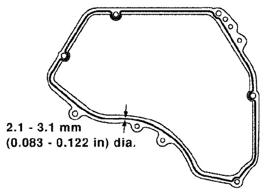

Use Genuine RTV Silicone Sealant or equivalent. Refer to [Recommended Chemical Products and Sealants] Recommended Chemical Products and Sealants.
12) Tighten bolts in numerical order as shown.
13) Install intake valve timing control solenoid valve to intake valve timing control cover if removed.
14) Connect ground cables, and install harness clip.
15) Check and adjust valve clearance. Refer to [Service Data and Specifications] [1][2]Specifications.
16) Installation is in the reverse order of removal after this step.
NOTE:
If hydraulic pressure inside timing chain tensioner drops after removal and installation, slack in the guide may generate a pounding noise during and just after the engine start. However, this is normal. Noise will stop after hydraulic pressure rises.
Inspection after Installation
Inspection of Camshaft Sprocket (INT) Oil Groove
CAUTION:
- Perform this inspection only when DTC P0011 is detected in "DTC check" of SDT and it is directed according to inspection procedure of Section 1A. Refer to [P0011 IVT Control] P0011.
- Check when the engine is cold so as to prevent burns from any splashing engine oil.
1) Check the engine oil level. Refer to [Engine Oil: Inspection] Testing and Inspection.
2) Perform the following procedure so as to prevent the engine from being unintentionally started while checking.
a) Release fuel pressure. Refer to [Fuel Pressure Check: QR25DE] Testing and Inspection.
b) Disconnect ignition coil and injector harness connectors.
c) Remove drive belt. Refer to [Drive Belts: Removal and Installation] Removal and Installation.
3) Remove intake valve timing control solenoid valve. Refer to [Timing Chain: Exploded View] Exploded View.
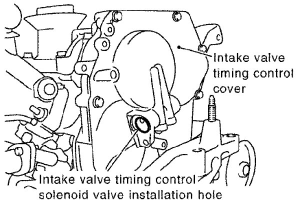
4) Crank the engine, and then make sure that engine oil comes out from intake valve timing control cover oil hole. Stop cranking after checking.
WARNING:
Be careful not to touch rotating parts (drive belt, idler pulley, and crankshaft pulley, etc.).
CAUTION:
Engine oil may squirt from intake valve timing control solenoid valve installation hole during cranking. Use a shop cloth to protect the engine components and the vehicle. Do not allow engine oil to get on rubber components such as drive belt or engine mount insulators. Immediately wipe off any splashed engine oil.
- Clean oil groove between oil strainer and intake valve timing control solenoid valve if engine oil does not come out from intake valve timing control cover oil hole. Refer to [Lubrication Circuit] Lubrication Circuit.
5) Remove components between intake valve timing control solenoid valve and camshaft sprocket (INT), and then check each oil groove for clogging.
- Clean oil groove if necessary. Refer to [Lubrication Circuit] Lubrication Circuit.
6) Installation is in the reverse order of removal.