Diagnosis Procedure
DIAGNOSIS PROCEDURE CHART
| Step |
Action |
YES |
NO |
| 1 |
CHECK COMBINATION METER INPUT SIGNAL
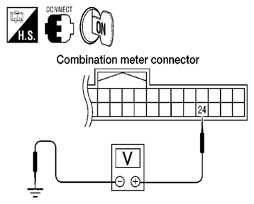
- Turn ignition switch ON.
 Courtesy of SUZUKI OF AMERICA CORP. Courtesy of SUZUKI OF AMERICA CORP.
- 2. Check voltage between combination meter harness connector M24 terminal 24 and ground.
24 - Ground
When driver seat belt is fastened: Approx. 12V
When driver seat belt is unfastened: Approx. 0V
Is the inspection result normal? |
Replace combination meter. Refer to
[COMBINATION METER: REMOVAL AND INSTALLATION ]. |
GO TO 2 |
| 2 |
CHECK SEAT BELT BUCKLE SWITCH CIRCUIT
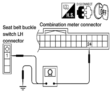
- Turn ignition switch OFF.
 Courtesy of SUZUKI OF AMERICA CORP. Courtesy of SUZUKI OF AMERICA CORP.
- 2. Disconnect combination meter and seat belt buckle switch LH.
- 3. Check continuity between combination meter harness connector M24 terminal 24 and seat belt buckle switch LH harness connector B12 terminal 1.
24 - 1: Continuity should exist.
- 4. Check continuity between combination meter harness connector M24 terminal 24 and ground.
24 - Ground: Continuity should not exist.
Is the inspection result normal? |
GO TO 3 |
Repair or replace harness. |
| 3 |
CHECK SEAT BELT BUCKLE SWITCH GROUND CIRCUIT
Check continuity between seat belt buckle switch LH harness connector B12 terminal 2 and ground.
2 - Ground: Continuity should exist.
Is the inspection result normal? |
Inspection End. |
Repair or replace harness. |