Camshaft: Service and Repair
Camshaft and Valve Lash Adjuster ReplacementRemoval
1. Remove engine assembly from vehicle.
2. Remove oil pan.
3. Remove cylinder head cover.
4. Remove timing chain cover.
5. Remove 2nd timing chain.
6. Remove CMP sensor.
7. To secure work in the following steps, reinstall mounting member, engine front torque bush, rear mounting and rear mounting No.2 bracket.
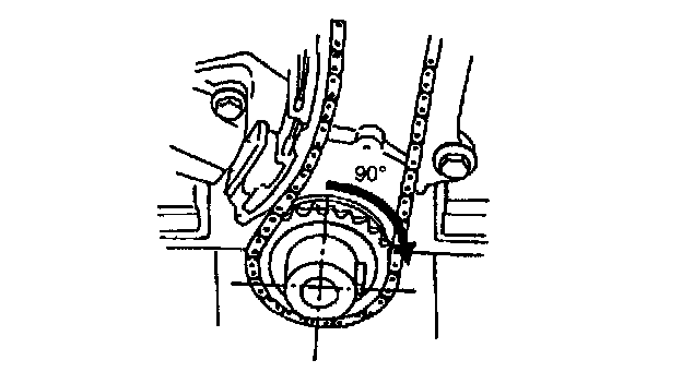
8. Set key on crankshaft in position as shown by turning crankshaft. This is to prevent interference between valves and piston.
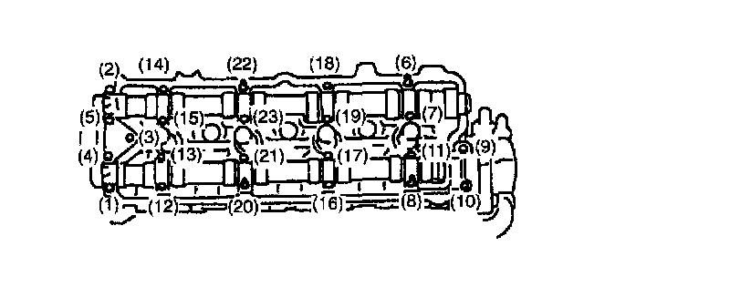
9. Loosen camshaft housing bolts in such order as indicated in figure and remove them.
10. Remove camshaft housings
11. Remove camshafts.
12. Remove valve lash adjusters (2).
NOTE:
^ Never disassemble hydraulic valve lash adjuster.
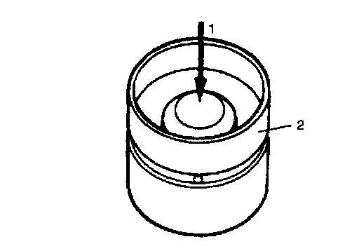
^ Don't apply force (1) to body of adjuster, oil in high pressure chamber in adjuster will leak.
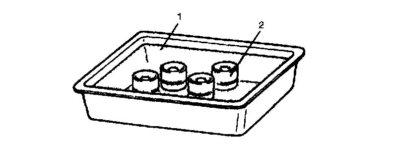
^ Immerse removed adjuster (2) in clean engine oil (1) and keep it there till reinstalling it so as to prevent oil leakage. If it is left in air, place it with its bucket body facing down. Don't place on its side or with bucket body facing up.
Installation
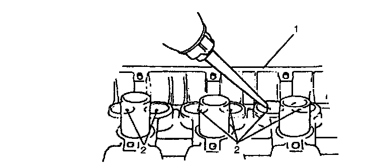
1. Before installing valve lash adjuster to cylinder head (1), fill oil passage of cylinder head with engine oil according to following procedure.
Pour engine oil through oil holes (2) and check that oil comes out from oil holes in sliding part of valve lash adjuster
Perform this check on both intake and exhaust sides
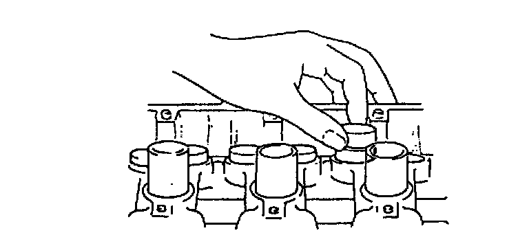
2. Install valve lash adjusters to cylinder head.
Apply engine oil around valve lash adjuster and then install it to cylinder head.
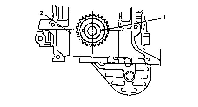
3. Match matchmark (1) on crank timing sprocket and mating surface of cylinder block and lower crankcase (2).
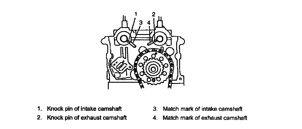
4. Install camshafts.
Apply oil to sliding surface of each camshaft and camshaft journal then install them by aligning match marks on cylinder head and camshafts as shown in figure.
NOTE: Install camshaft in such direction that its end with groove for CMP sensor installation comes to exhaust side.
5. Install camshaft housing pins (3) as shown in figure.
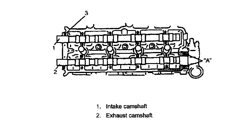
6. Apply sealant "A" to exhaust camshaft end housing sealing surface area as shown in figure.
"A": Sealant 99000-31150
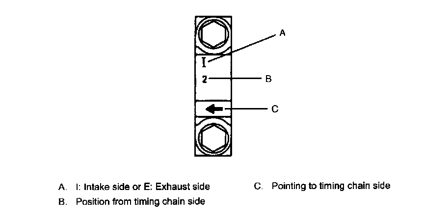
7. Check position of camshaft housings.
Embossed marks are provided on each camshaft housing, indicating position and direction for installation. Install housings as indicated by these marks.

8. After applying oil to housing bolts, tighten them temporarily first. Then tighten them by following numerical order in figure.
Tighten a little at a time and evenly among bolts and repeat tightening sequence two or three times before they are tightened to specified torque.
Tightening torque
Camshaft housing bolts (a): 11 Nm (1.1 kgf-m, 8.0 ft. lbs.)
9. Install CMP sensor.
10. Install 2nd timing chain.
11. Install timing chain cover.
12. Install cylinder head cover.
13. Install oil pan.
14. Install engine assembly to vehicle.
CAUTION:
^ Don't turn camshafts or start engine (i.e., valves should not be operated) for about half an hour after reinstalling hydraulic valve lash adjusters and camshafts. As it takes time for valves to settle in place, operating engine within half an hour after their installation may cause interference to occur between valves themselves or valves and piston.
^ If air is trapped in valve lash adjuster, valve may make tapping sound when engine is operated after valve lash adjuster is installed. In such a case, run engine for about half an hour at about 2,000 to 3,000 r/min., and then air will be purged and tapping sound will cease. Should lopping sound not cease, it is possible that valve lash adjuster is defective. Replace it if defective. If defective adjuster can't be located by hearing among 16 of them, check as follows.
- Stop engine and remove cylinder head cover.
- Push adjuster downward by hand (with less than 20 kg or 44 lbs. force) when cam crest is not on adjuster to be checked and check if clearance exists between cam and adjuster. If it does, adjuster is defective and needs replacement.
Inspection
Cam wear
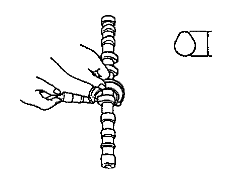
Using a micrometer, measure cam height. If measured height is below its limit, replace camshaft.

Cam height
Camshaft runout
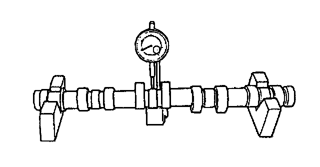
Set camshaft between two "V" blocks, and measure its runout by using a dial gauge.
If measured runout exceeds the specified limit, replace camshaft.
Runout limit 0.10 mm (0.0039 inch)
Camshaft journal wear
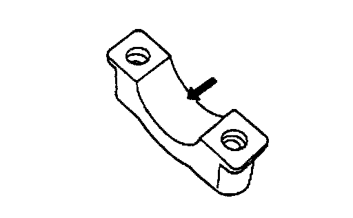
Check camshaft journals and camshaft housings for pitting, scratches, wear or damage.
If any malcondition is found, replace camshaft or cylinder head with housing. Never replace cylinder head without replacing housings.
Check clearance by using gauging plastic. Checking procedure is as follows.
1. Clean housings and camshaft journals.
2. Make sure that all valve lash adjusters are removed and install camshaft to cylinder head.
3. Place a piece of gauging plastic to full width of journal of camshaft (parallel to camshaft).
4. Install camshaft housing.
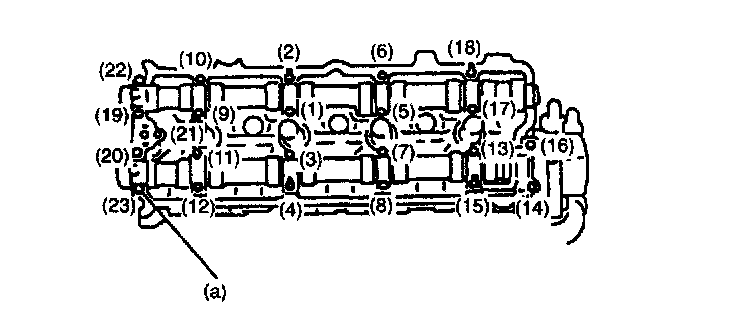
5. Tighten camshaft housing bolts in such order as indicated in figure a little at a time till they are tightened to specified torque.
NOTE: Do not rotate camshaft while gauging plastic is installed.
Tightening torque
Camshaft housing bolts (a): 11 Nm (1.1 kgf-m, 8.0 ft. lbs.)
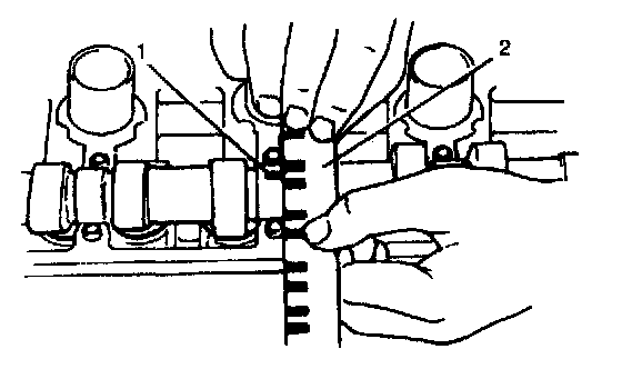
6. Remove housing, and using scale (2) on gauging plastic envelop (1), measure gauging plastic width at its widest point.

Journal clearance
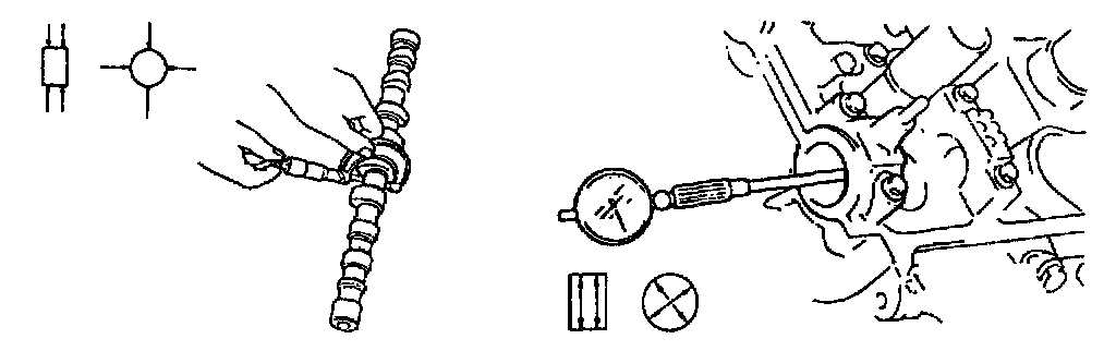
If measured camshaft journal clearance exceeds limit, measure journal (housing) bore and outside diameter of camshaft journal. Replace camshaft or cylinder head assembly whichever the difference from specification is greater.

Camshaft journal
Wear of hydraulic valve lash adjuster
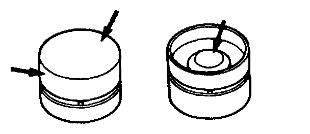
Check adjuster for pitting, scratches, or damage.
If any malcondition is found, replace.
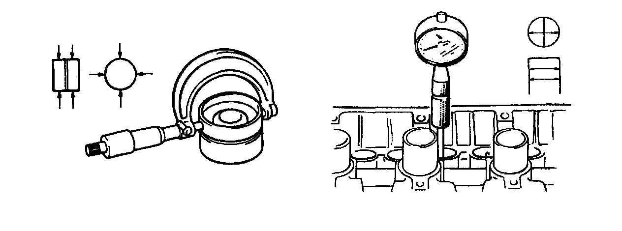
Measure cylinder head bore and adjuster outside diameter to determine cylinder head-to-adjuster clearance. If clearance exceeds limit, replace adjuster or cylinder head.

Cylinder head bore and adjuster outside diameter
Oil relief valve
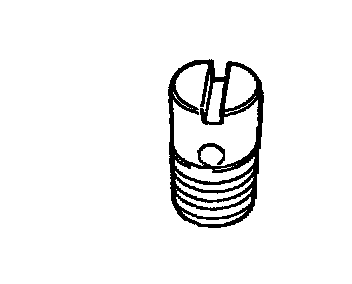
Check oil relief valve for clogging and ball for being stuck.