- Removal of aspirator (for automatic air conditioning system)
- Release the 2 claws and remove the aspirator.
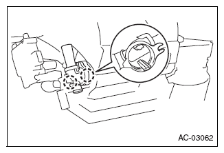 Courtesy of SUBARU OF AMERICA, INC.
- Removal of air conditioner radiator damper servo sub-assembly NO. 1
- Remove the 2 screws and remove the air conditioner radiator damper servo sub-assembly NO. 1.
 Courtesy of SUBARU OF AMERICA, INC.
- Removal of air conditioner radiator damper servo sub-assembly NO. 5 (for automatic air conditioning system)
- Remove the 2 screws and remove the air conditioner radiator damper servo sub-assembly NO. 5.
CAUTION:
When reusing air conditioner radiator damper servo sub-assembly NO. 5, set the controller position to MAXCOOL on the vehicle before removal and hold it for 30 seconds after setting.
 Courtesy of SUBARU OF AMERICA, INC.
- Removal of heater cover (for automatic air conditioning system)
- Remove the 3 screws and remove the heater cover.
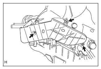 Courtesy of SUBARU OF AMERICA, INC.
- Removal of heater cover (for manual air conditioning system)
NOTE:
Repeat the same removal steps for the automatic air conditioning system.
- Removal of heater radiator unit sub-assembly (for automatic air conditioning system)
- Remove the screw and remove the clamp.
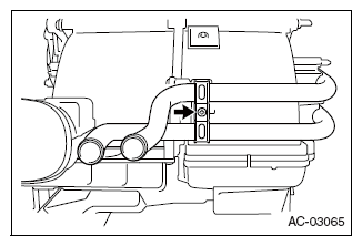 Courtesy of SUBARU OF AMERICA, INC.
- Slide the heater radiator unit sub-assembly in the direction of the arrow in the figure to remove it.
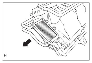 Courtesy of SUBARU OF AMERICA, INC.
- Removal of heater radiator unit sub-assembly (for manual air conditioning system)
NOTE:
Repeat the same removal steps for the automatic air conditioning system.
- Removal of air filter case
- Release the 2 claws and remove the air filter case.
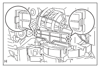 Courtesy of SUBARU OF AMERICA, INC.
- Removal of clean air filter
- Slide the clean air filter in the direction of the arrow in the figure to remove it.
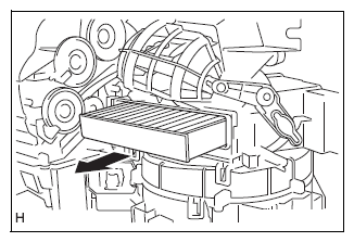 Courtesy of SUBARU OF AMERICA, INC.
- Removal of cooling unit case
- Remove the 2 screws.
- Release the 4 claws and remove the cooling unit case.
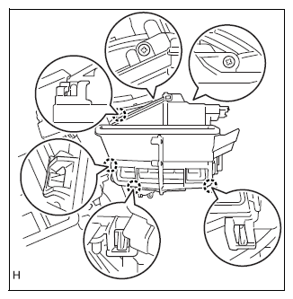 Courtesy of SUBARU OF AMERICA, INC.
- Removal of cooler expansion valve (for automatic air conditioning system)
- Remove the gasket.
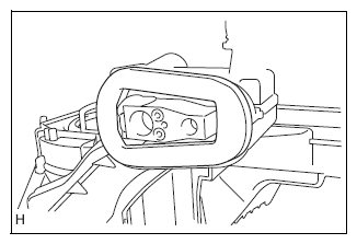 Courtesy of SUBARU OF AMERICA, INC.
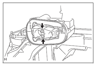
- Using hexagon socket wrench 4, remove the 2 hexagon bolts and the cooler expansion valve.
 Courtesy of SUBARU OF AMERICA, INC.
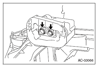
- Remove the 2 O-rings from cooler evaporator NO. 1.
 Courtesy of SUBARU OF AMERICA, INC.
- Removal of cooler expansion valve (for manual air conditioning system)
NOTE:
Repeat the same removal steps for the automatic air conditioning system.
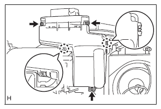
- Removal of cover
- Remove the 3 screws.
- Release the 2 claws and remove the cover.
 Courtesy of SUBARU OF AMERICA, INC.
- Removal of cooler unit drain hose NO. 1
- Remove cooler unit drain hose NO. 1.
 Courtesy of SUBARU OF AMERICA, INC.
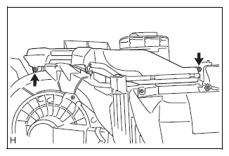
- Removal of air duct NO. 1
- Remove the 2 screws and remove air duct NO. 1.
 Courtesy of SUBARU OF AMERICA, INC.
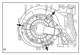
- Removal of blower motor sub-assembly (with fan)
- Remove the 3 screws, and remove the blower motor sub-assembly (with fan).
 Courtesy of SUBARU OF AMERICA, INC.
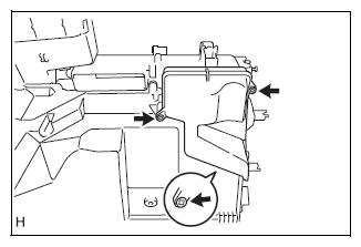
- Removal of air duct NO. 2
- Remove the 3 screws and remove air duct NO. 2.
 Courtesy of SUBARU OF AMERICA, INC.
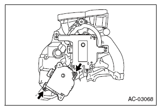
- Removal of air conditioner radiator damper servo sub-assembly NO. 4 (for automatic air conditioning system)
- Remove the 2 screws, and remove the air conditioner radiator damper servo sub-assembly NO. 4.
CAUTION:
When reusing air conditioner radiator damper servo sub-assembly NO. 4, set the controller position to the servo motor opening angle 32.42 % on the vehicle before removal and hold it for 30 seconds after setting.
 Courtesy of SUBARU OF AMERICA, INC.
- Removal of air conditioner radiator damper servo sub-assembly NO. 3 (for automatic air conditioning system)
- Remove the 3 screws, and remove the air conditioner radiator damper servo sub-assembly NO. 3.
 Courtesy of SUBARU OF AMERICA, INC.
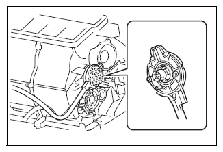
- Removal of air outlet damper control cable sub-assembly (for manual air conditioning system)
- Release the 3 claws and remove the air outlet damper control cable sub-assembly.
CAUTION:
Hold the control cable and remove it slowly so that the drive gear at the unit may not be pulled.
 Courtesy of SUBARU OF AMERICA, INC.
- Removal of heater control cable sub-assembly (for manual air conditioning system)
- Release the 3 claws and remove the heater control cable sub-assembly.
CAUTION:
Hold the control cable and remove it slowly so that the drive gear at the unit may not be pulled.
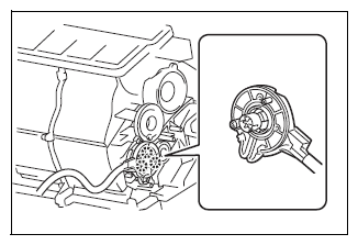 Courtesy of SUBARU OF AMERICA, INC.
- Removal of cooling unit case (for automatic air conditioning system)
- Disconnect the clamp.
 Courtesy of SUBARU OF AMERICA, INC.
- Remove the 7 screws.
- Release the 2 claws and remove the cooling unit case.
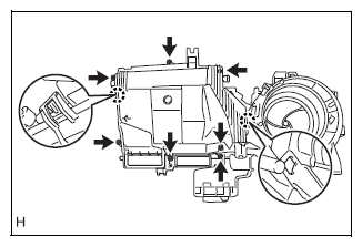 Courtesy of SUBARU OF AMERICA, INC.
- Removal of cooling unit case (for manual air conditioning system)
NOTE:
Repeat the same removal steps for the automatic air conditioning system.
- Removal of cooler evaporator NO. 1 (for automatic air conditioning system)
- Remove cooler evaporator NO. 1.
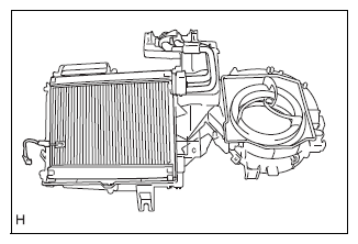 Courtesy of SUBARU OF AMERICA, INC.
- Removal of cooler evaporator NO. 1 (for manual air conditioning system)
NOTE:
Repeat the same removal steps for the automatic air conditioning system.
- Removal of cooler thermistor NO. 1 (for automatic air conditioning system)
- Remove the cooler thermistor NO. 1.
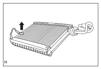 Courtesy of SUBARU OF AMERICA, INC.
- Removal of cooler thermistor NO. 1 (for manual air conditioning system)
NOTE:
Repeat the same removal steps for the automatic air conditioning system.
- Removal of air conditioner tube assembly (for automatic air conditioning system)
- Using hexagon socket wrench 4, remove the 2 hexagon bolts and the air conditioner tube assembly.
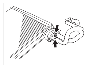 Courtesy of SUBARU OF AMERICA, INC.
- Removal of air conditioner tube assembly (for manual air conditioning system)
NOTE:
Repeat the same removal steps for the automatic air conditioning system.
- Removal of blower motor control (for automatic air conditioning system)
- Remove the 2 screws and remove the blower motor control.
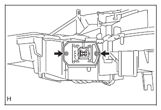 Courtesy of SUBARU OF AMERICA, INC.
- Removal of blower register (for manual air conditioning system)
NOTE:
Repeat the same removal steps for the blower motor control.
- Removal of cooler blower case
- Remove the 4 screws and release the 2 claws.
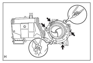 Courtesy of SUBARU OF AMERICA, INC.
- Remove the cooler blower case from the heater case lower.
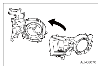 Courtesy of SUBARU OF AMERICA, INC.
- Removal of cooler unit case gasket (for automatic air conditioning system)
- Remove the cooler unit spacer.
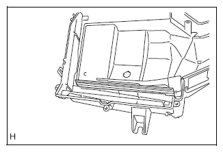 Courtesy of SUBARU OF AMERICA, INC.
- Removal of cooler unit case gasket (for manual air conditioning system)
NOTE:
Repeat the same removal steps for the automatic air conditioning system.
- Removal of cover plate
- Remove the cover plate.
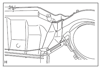 Courtesy of SUBARU OF AMERICA, INC.