ECM Terminal Arrangement
- Instrument panel junction block ASSY, Main body ECM (multiplex network body computer)
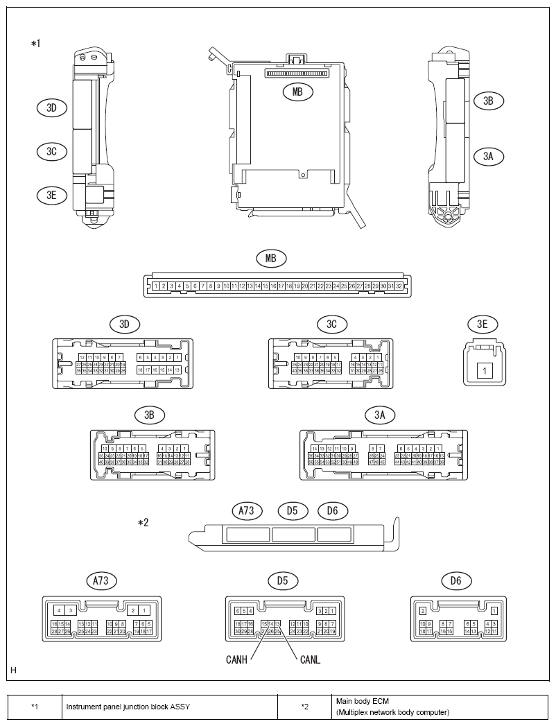 Courtesy of SUBARU OF AMERICA, INC.
- Check the main body ECM (multiplex network body computer)
- Remove the main body ECM (Multiplex network body computer). (Refer to
REMOVAL
)
- Measure the voltage and resistance between terminals.
STANDARD VALUE
| Terminal No. |
Item |
Inspection conditions |
Standard value |
| MB-1 - chassis ground |
Voltage |
Always |
11 to 14V |
| MB-8 - chassis ground |
Voltage |
IG ON |
11 to 14V |
| MB-11 - chassis ground |
Resistance |
Always |
Less than 1 Ω |
| MB-32 - chassis ground |
Voltage |
Always |
11 to 14V |
- Install the main body ECM (Multiplex network body computer).
- Measure the waveform between terminals using an oscilloscope.
STANDARD VALUE
| Terminal No. |
Item |
Inspection conditions |
Standard value |
| D5-4 - D6-1 |
Waveform |
IG ON |
Pulse generation |
- Power window regulator master switch ASSY
 Courtesy of SUBARU OF AMERICA, INC.
- Check the power window regulator master switch ASSY
- Disconnect the connector F6 from the power window regulator master switch ASSY.
- Measure the voltage and resistance between terminals.
STANDARD VALUE
| Terminal No. |
Item |
Inspection conditions |
Standard value |
| F6-5 - chassis ground |
Resistance |
Always |
Less than 1 Ω |
| F6-12-F6-5 |
Voltage |
Always |
11 to 14V |
- Power window regulator switch ASSY
 Courtesy of SUBARU OF AMERICA, INC.
- Inspection of the power window regulator switch ASSY
- Disconnect the connector E8 from the power window regulator switch ASSY.
- Measure the voltage and resistance between terminals.
STANDARD VALUE
| Terminal No. |
Item |
Inspection conditions |
Standard value |
| F8-5 - chassis ground |
Resistance |
Always |
Less than 1 Ω |
| E8-12-E8-5 |
Voltage |
Always |
11 to 14V |
- Collation ECM (Smart key computer ASSY) (with smart entry)
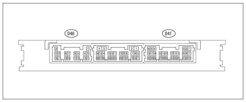 Courtesy of SUBARU OF AMERICA, INC.
- Check the collation ECM (Smart key computer ASSY)
- Disconnect the connectors D41 and D48 from the collation ECM (Smart key computer ASSY).
- Measure the voltage and resistance between terminals.
STANDARD VALUE
| Terminal No. |
Item |
Inspection conditions |
Standard value |
| D41-5-D48-11 |
Voltage |
IG ON |
11 to 14V |
| D48-2-D48-11 |
Voltage |
Always |
11 to 14V |
| D48-11 - chassis ground |
Resistance |
Always |
Less than 1 Ω |
- Steering lock actuator ASSY (with smart entry)
 Courtesy of SUBARU OF AMERICA, INC.
- Check the steering lock actuator ASSY
- Disconnect the connector D59 from the steering lock actuator ASSY.
- Measure the voltage and resistance between terminals.
STANDARD VALUE
| Terminal No. |
Item |
Inspection conditions |
Standard value |
| D59-1 - chassis ground |
Resistance |
Always |
Less than 1 Ω |
| D59-6 - D59-1 |
Voltage |
IG ON |
11 to 14V |
| D59-7 - D59-1 |
Voltage |
Always |
11 to 14V |
- ID code box (Immobilizer code ECM) (with ID code box)
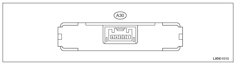 Courtesy of SUBARU OF AMERICA, INC.
- Check the ID code box
- Disconnect the connector A30 of the ID code box.
- Measure the voltage between the terminals.
STANDARD VALUE
| Terminal No. |
Item |
Inspection conditions |
Standard value |
| A30-1 - A30-5 |
Voltage |
Always |
11 to 14 V |
| A30-5 - chassis ground |
Voltage |
Always |
11 to 14 V |