DTC P0843 Secondary Oil Pressure Sensor Circuit (High): Wiring Diagram
CVT Control System. See appropriate SYSTEM WIRING DIAGRAM article.
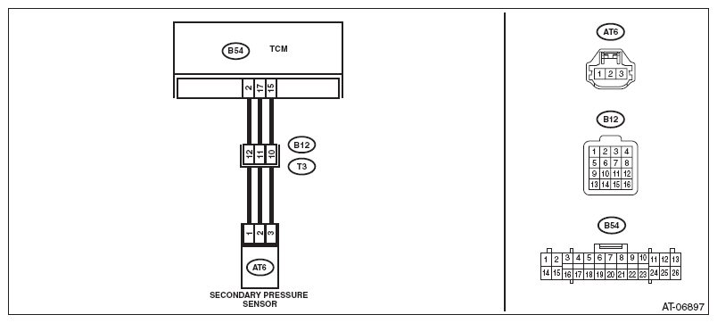 Courtesy of SUBARU OF AMERICA, INC.
 DIAGNOSTIC PROCEDURE
| Step |
Check |
Yes |
No |
1 CHECK INPUT SIGNAL FOR TCM.
- Start the engine.
- Warm up until the ATF temperature reaches to 40 - 70°C (104 - 158°F).
- Shift the select lever to "P" range.
- Stabilize the engine speed at idle.
- Read the data of «Actual secondary pressure» using Subaru Select Monitor.
|
Is the «Actual secondary pressure» 0.5 - 1.5 MPa? |
Check for poor contact of connector. |
Go to step 2
. |
2 CHECK HARNESS.
- Turn the ignition switch to OFF.
- Disconnect the TCM and transmission connectors.
- Turn the ignition switch to ON.
- Measure the voltage between TCM connector and chassis ground.
Connector & terminal
(B54) No. 2 (+) - Chassis ground (-):
(B54) No. 17 (+) - Chassis ground (-):
|
Is the voltage approx. 0 V? |
Go to step 3
. |
Repair the short circuit of harness. |
3 CHECK HARNESS.
- Turn the ignition switch to OFF.
- Measure the resistance between TCM connector terminals.
Connector & terminal
(B54) No. 2 - (B54) No. 17:
|
Is the resistance less than 1 Ω? |
Repair the short circuit of harness. |
Go to step 4
. |
4 CHECK TRANSMISSION HARNESS.
- Disconnect the secondary pressure sensor connector.
- Turn the ignition switch to ON.
- Measure the voltage between transmission connector and chassis ground.
Connector & terminal
(T3) No. 11 (+) - Chassis ground (-):
(T3) No. 12 (+) - Chassis ground (-):
|
Is the voltage approx. 0 V? |
Go to step 5
. |
Repair the short circuit of harness. |
5 CHECK TRANSMISSION HARNESS.
- Turn the ignition switch to OFF.
- Measure the resistance between transmission connector terminals.
Connector & terminal
(T3) No. 11 - (T3) No. 12:
|
Is the resistance less than 1 Ω? |
Repair the short circuit of harness. |
Go to step 6
. |
6 CHECK SENSOR POWER SUPPLY.
- Connect the connectors of TCM and transmission.
- Turn the ignition switch to ON.
- Measure the voltage between secondary pressure sensor connector terminals.
Connector & terminal
(AT6) No. 1 (+) - (AT6) No. 3 (-):
|
Is the voltage 4.5 V or more? |
Replace the secondary pressure sensor. Refer to
SECONDARY PRESSURE SENSOR
. |
Check for poor contact of the connector, and repair the defective part. |