DTC P0771 Shift Solenoid "E" Performance Or Stuck Off: Wiring Diagram
WARNING: This page is about a different variant/trim than selected.
AT Control System. Refer to appropriate SYSTEM WIRING DIAGRAM article.
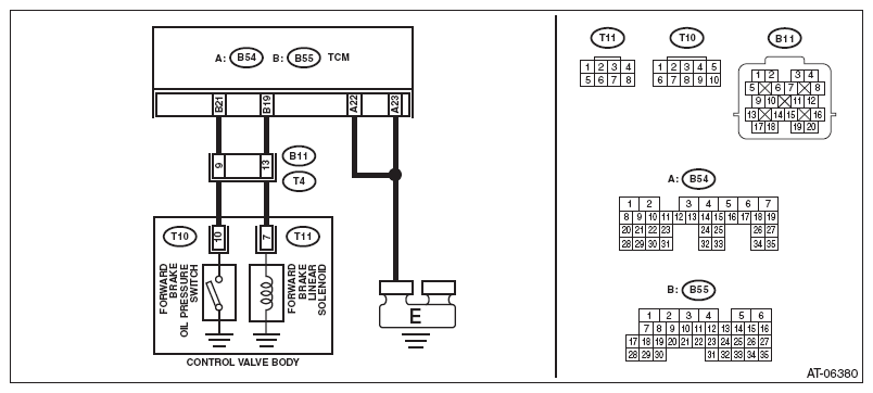 Courtesy of SUBARU OF AMERICA, INC.
 DIAGNOSTIC PROCEDURE
| Step |
Check |
Yes |
No |
1 CHECK HARNESS CONNECTOR BETWEEN TCM AND TRANSMISSION.
- Turn the ignition switch to OFF.
- Disconnect the connectors from TCM and transmission.
- Measure the resistance of harness between TCM connector and transmission connector.
Connector & terminal
(B54) No. 22 - Chassis ground:
(B54) No. 23 - Chassis ground:
(B55) No. 19 - (B11) No. 13:
(B55) No. 21 - (B11) No. 9:
|
Is the resistance less than 1 Ω? |
Go to step 2
. |
Repair the open circuit of harness between TCM and transmission connector. |
2 CHECK HARNESS CONNECTOR BETWEEN TCM AND CHASSIS GROUND.
Measure the resistance between TCM connector and chassis ground.
Connector & terminal
(B55) No. 21 - Chassis ground: |
Is the resistance 1 MΩ or more? |
Go to step 3
. |
Repair the short circuit of harness between TCM and transmission connector. |
3 CHECK INPUT SIGNAL FOR TCM.
- Connect all connectors.
- Turn the ignition switch to ON.
- Read the data of «Fwd/B hydraulic pressure SW» using Subaru Select Monitor.
|
Is "OFF" displayed? |
Go to step 4
. |
Go to step 6
. |
4 CHECK INPUT SIGNAL FOR TCM.
- Turn the ignition switch to OFF.
- Start the engine.
- Drive the vehicle on 2nd speed of manual mode at 15 km/h (9 MPH) with checking current gear position using Subaru Select Monitor.
- Read the data of «Fwd/B hydraulic pressure SW» using Subaru Select Monitor.
|
Is "ON" displayed? |
Check for poor contact of harness in the solenoid output and oil pressure SW input, and repair the defective part. |
Go to step 5
. |
5 CHECK HARNESS CONNECTOR BETWEEN TRANSMISSION AND CONTROL VALVE BODY.
- Turn the ignition switch to OFF.
- Disconnect the connector from transmission.
- Remove the transmission connector from bracket.
- Lift up the vehicle.
- Drain the ATF.
CAUTION:
Do not drain ATF until it cools down.
- Remove the oil pan.
- Disconnect the control valve body connector.
- Measure the resistance between transmission connector and control valve body connector.
Connector & terminal
(T4) No. 9 - (T10) No. 10:
(T4) No. 13 - (T11) No. 7:
|
Is the resistance less than 1 Ω? |
Replace the control valve body. Refer to
CONTROL VALVE BODY
. |
Replace the transmission harness assembly. |
6 CHECK HARNESS CONNECTOR BETWEEN TRANSMISSION AND CONTROL VALVE BODY.
- Turn the ignition switch to OFF.
- Disconnect the connector from transmission.
- Remove the transmission connector from bracket.
- Lift up the vehicle.
- Drain the ATF.
CAUTION:
Do not drain ATF until it cools down.
- Remove the oil pan.
- Disconnect the control valve body connector.
- Measure the resistance between transmission ground and control valve body connector.
Connector & terminal
(T10) No. 10 - Transmission ground:
|
Is the resistance 1 MΩ or more? |
Replace the control valve body. Refer to
CONTROL VALVE BODY
. |
Replace the transmission harness assembly. |