DTC 26 Passenger's Airbag Indicator Failure: Wiring Diagram
WARNING: This page is about a different car, the 2013 Subaru Forester. However, it is still accessible from the selected car via links, so may be relevant.
Airbag system < Refer to appropriate SYSTEM WIRING DIAGRAM. >
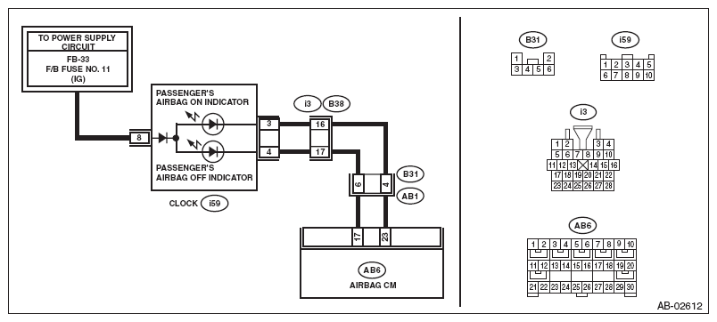 Courtesy of SUBARU OF AMERICA, INC.
| Step |
Check |
Yes |
No |
1 CHECK FOR POOR CONTACT.
- Turn the ignition switch to OFF, disconnect the battery ground cable, and wait for 60 seconds or more.
- Confirm that firm contact is secured for the connector between the airbag control module and the clock.
|
Is there poor contact of any connector? |
Repair the bulkhead harness. Or replace the airbag main harness along with body harness. |
Go to step 2
. |
2 CHECK AIRBAG MAIN HARNESS.
- Disconnect the connectors (AB6, AB17, AB18) from airbag control module.
- Connect the battery ground terminal and turn the ignition switch to ON.
NOTE:
Neither of ON/OFF illuminates when it is normal.
|
Does the passenger's airbag indicator illuminate? |
Go to step 3
. |
Go to step 4
. |
3 CHECK AIRBAG MAIN HARNESS.
- Turn the ignition switch to OFF.
- Remove the clock and disconnect the connector (i59).
- Connect the connector (1AG) in the test harness AG to the connectors (AB6, AB17, AB18).
- Measure the resistance between connector (2AG) in the test harness AG and chassis ground.
Connector & terminal
(2AG) No. 9 - (2AG) No. 8:
(2AG) No. 9 - Chassis ground:
(2AG) No. 8 - Chassis ground:
|
Is the resistance 1 MΩ or more? |
Replace the clock. < Refer to
REMOVAL
, Clock. > |
Repair the bulkhead harness. Or replace the airbag main harness along with body harness. |
4 CHECK AIRBAG HARNESS.
- Turn the ignition switch to OFF.
- Connect the connector (1AG) in the test harness AG to the connectors (AB6, AB17, AB18).
- Connect the connectors (7AG) and (8AG) in the test harness AG.
- Connect the battery ground terminal and turn the ignition switch to ON.
|
Does the passenger's airbag indicator illuminate? |
Replace the airbag control module. < Refer to
AIRBAG CONTROL MODULE
. > |
Go to step 5
. |
5 CHECK AIRBAG HARNESS.
- Turn the ignition switch to OFF.
- Remove the clock and disconnect the connector (i59).
- Measure the resistance between connector (2AG) in the test harness AG and connector (i59).
Connector & terminal
(2AG) No. 9 - (i59) No. 4:
(2AG) No. 8 - (i59) No. 3:
|
Is the resistance less than 10 Ω? |
Go to step 6
. |
Repair the bulkhead harness. Or replace the airbag main harness along with body harness. |
6 CHECK BODY HARNESS.
- Turn the ignition switch to ON.
- Measure the voltage between connector (i59) and chassis ground.
Connector & terminal
(i59) No. 8 (+) - Chassis ground (-):
|
Is the voltage 10 V or more? |
Replace the clock. < Refer to
REMOVAL
, Clock. > |
Repair the clock power supply line. |