DTC P0031: Front Heated Oxygen Sensor (Ho2S) Heater Circuit Low Input - Legacy & Outback 2.5L A/T
- Perform basic diagnostic procedure. See BASIC DIAGNOSTIC PROCEDURE . If DTC P0141 and P1132 exist at the same time, go to next step. If only DTC P1132 exists, go to step 5.
- Turn ignition off. Disconnect front HO2S connector. Turn ignition on. Using DVOM connected to ground, measure voltage at front HO2S connector terminal No. 2. See Fig 1. If voltage is more than 10 volts, go to next step. If voltage is not more than 10 volts, locate and repair open circuit in wiring and check for proper terminal contact in connectors between front HO2S and main relay. See WIRING DIAGRAMS article.
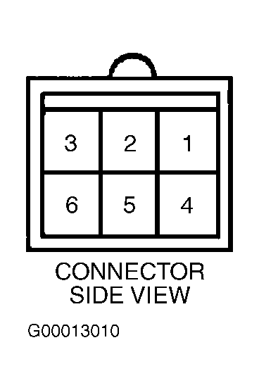 Courtesy of SUBARU OF AMERICA, INC.
- Turn ignition off. Using an ohmmeter connected to ground, backprobe ECM connector B134 (35-pin connector) terminal No. 35. See Figure. If resistance is less than 5 ohms, go to next step. If resistance is not less than 5 ohms, locate and repair open circuit in wiring and check for proper terminal contact in connectors between ECM and chassis ground point.
- Turn ignition off. Using an ohmmeter connected to ground, backprobe ECM connector B134 (35-pin connector) terminal No. 34. If resistance is less than 5 ohms, go to next step. If resistance is not less than 5 ohms, locate and repair open circuit in wiring and check for proper terminal contact in connectors between ECM and chassis ground point.
- Start engine. Using scan tool, observe front HO2S heater current value. If current draw is more than 0.2 amp, check for poor contact at ECM and HO2S connectors. If current draw is not more than 0.2 amp, go to next step.
- With engine idling, measure voltage between ground and ECM connector B134 (35-pin connector) terminal No. 22. If voltage is less than one volt, go to step 8. If voltage is not less than one volt, go to next step.
- With engine idling, measure voltage between ground and ECM connector B134 (35-pin connector) terminal No. 22 while wiggling harness and ECM connector. If voltage changes less than one volt while wiggling harness and connector, check for poor terminal contact at ECM connector. If voltage does not change less than one volt while wiggling harness and connector, go to next step.
- Measure voltage between ground and ECM connector B134 (35-pin connector) terminal No. 23. If voltage is less than one volt, go to step 10. If voltage is not less than one volt, go to next step.
- Measure voltage between ground and ECM connector B134 (35-pin connector) terminal No. 23 while wiggling harness and ECM connector. If voltage changes less than one volt while wiggling harness and connector, check for poor terminal contact at ECM connector. If voltage does not change less than one volt while wiggling harness and connector, go to next step.
- Turn ignition off. Measure resistance between front HO2S connector terminals No. 2 and No. 5. See Fig 1. If resistance is less than 10 ohms, locate and repair open or short to ground in wiring and check for proper terminal contact in connectors between ECM and front HO2S. If resistance is not less than 10 ohms, replace front HO2S. Clear memory and perform verification procedure. See CLEARING DIAGNOSTIC TROUBLE CODES and VERIFICATION PROCEDURE
.