Removal Procedure
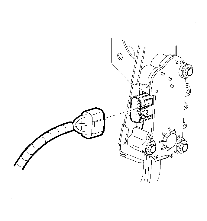 Courtesy of GENERAL MOTORS CORP.
- Disconnect the accelerator pedal assembly electrical connector.
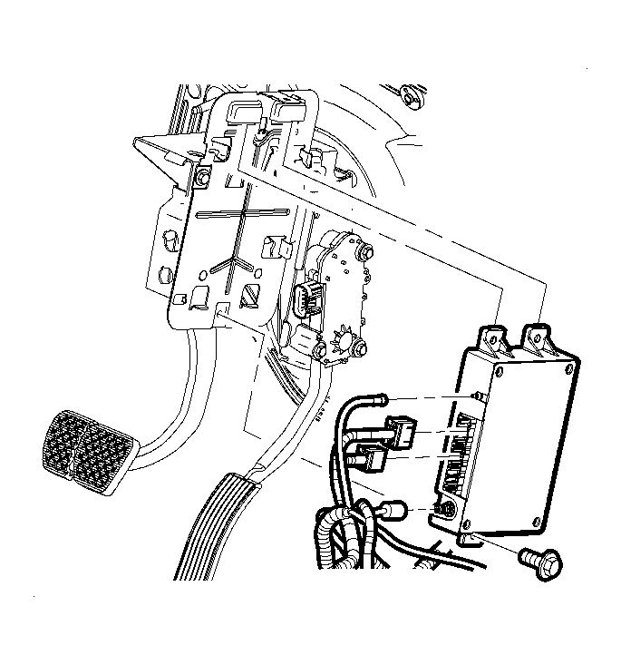 Courtesy of GENERAL MOTORS CORP.
- Remove the mounting bolts and reposition the OnStar® module aside, if equipped. Refer to Communication Interface Module Replacement
in Cellular Communication.
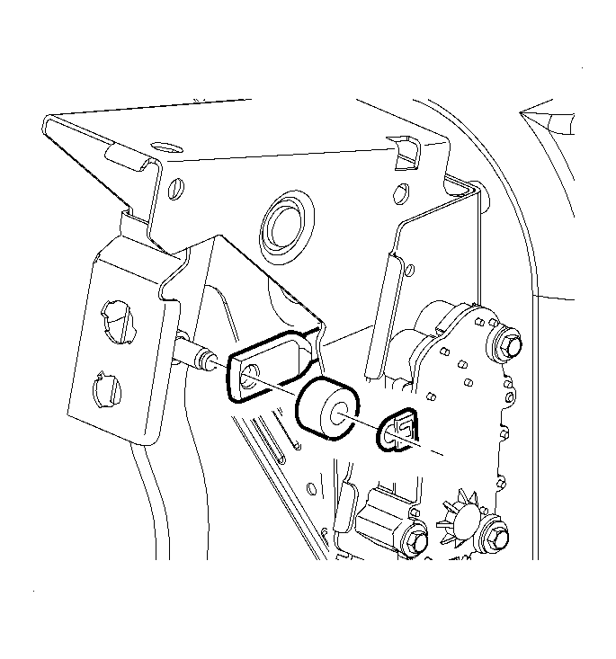 Courtesy of GENERAL MOTORS CORP.
- Remove the retaining clip and washer from the brake pedal.
- Release the brake booster pushrod from the brake pedal.
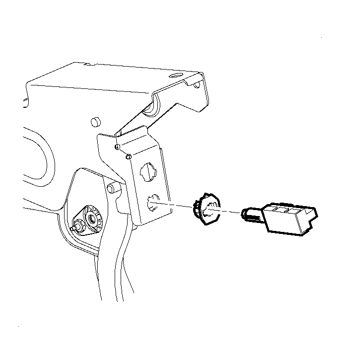 Courtesy of GENERAL MOTORS CORP.
- Remove the stop lamp switch from the pedal bracket. Refer to Stop Lamp Switch Replacement
in Lighting Systems.
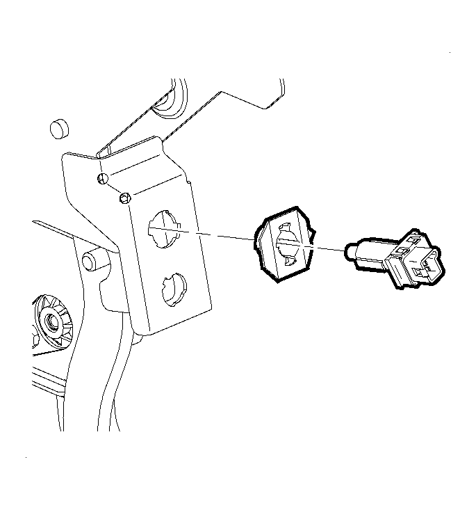 Courtesy of GENERAL MOTORS CORP.
- Remove the cruise control release switch, if equipped, from the pedal bracket. Refer to Cruise Release Switch Replacement
in Cruise Control.
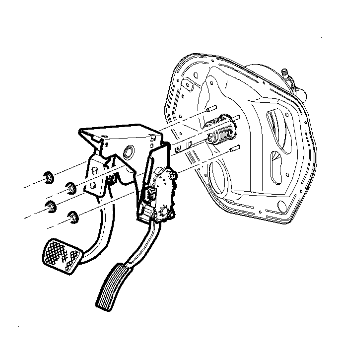 Courtesy of GENERAL MOTORS CORP.
- Remove the brake booster mounting nuts.
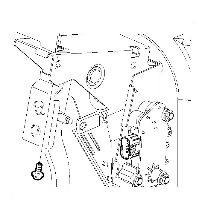 Courtesy of GENERAL MOTORS CORP.
- Remove the brake pedal bracket-to-steering column bracket bolt.
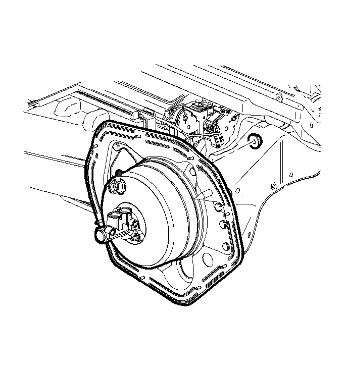 Courtesy of GENERAL MOTORS CORP.
- Loosen, but do not remove, the steering column bracket to cowl nut.
- While simultaneously disengaging the brake pedal bracket pilot bushings from the foam insulation panel, pull the brake pedal assembly back and toward the center of the vehicle.
- Remove the brake pedal assembly from the vehicle.
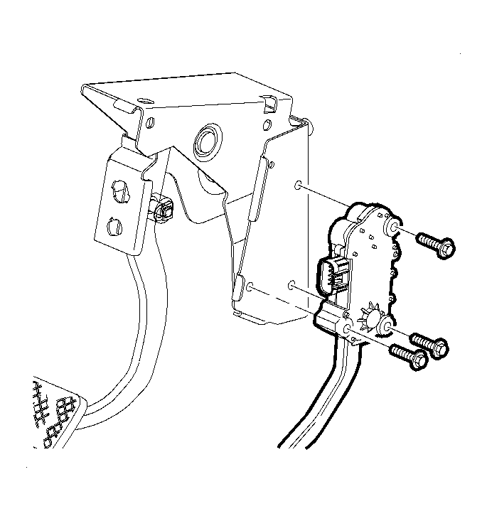 Courtesy of GENERAL MOTORS CORP.
- Remove the accelerator pedal assembly from the brake pedal bracket. Refer to Accelerator Pedal Position Assembly Replacement
in Engine Controls - 2.2L (L61) or Accelerator Pedal with Position Sensor Replacement
in Engine Controls - 3.5L (L66).
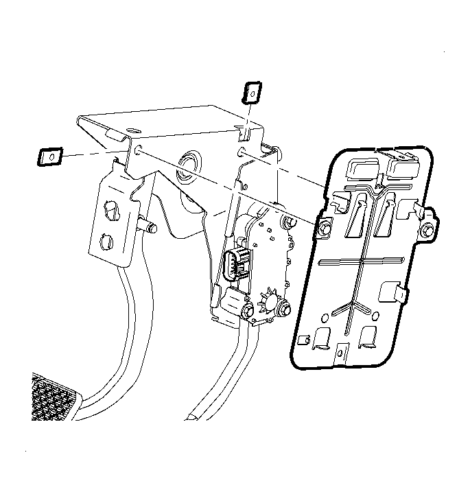 Courtesy of GENERAL MOTORS CORP.
- Remove the OnStar® mounting bracket bolts and J-nuts from the brake pedal assembly, if equipped.