Removal Procedure
- Remove the I/P retainer. Refer to Instrument Panel (I/P) Retainer Replacement .
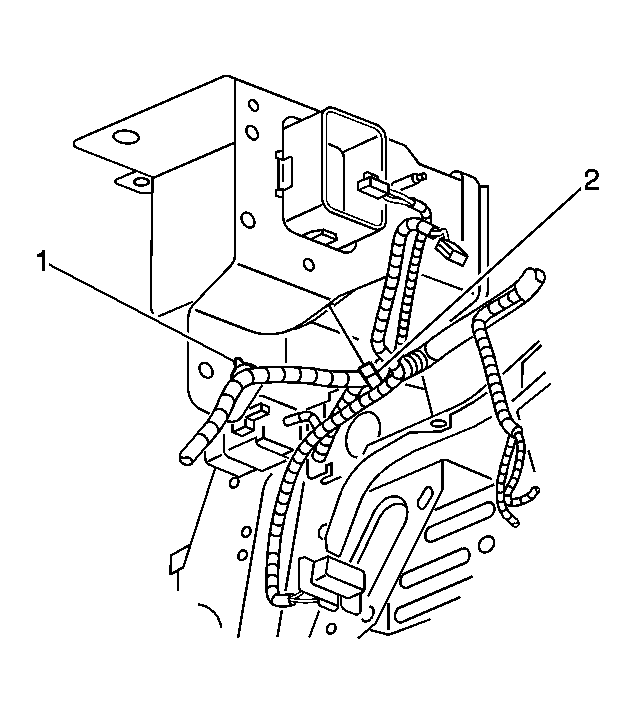 Courtesy of GENERAL MOTORS CORP.
- Remove the wire harness rosebuds (1,2) from the left side of the beam.
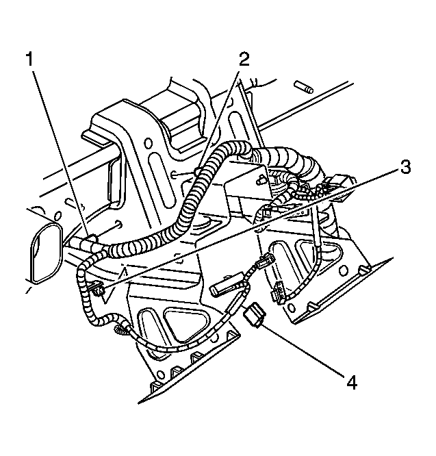 Courtesy of GENERAL MOTORS CORP.
- Remove the wire harness rosebuds (1,2,3) from the left side of the steering column support bracket.
- Remove the metal clip (4) from the steering column support bracket.
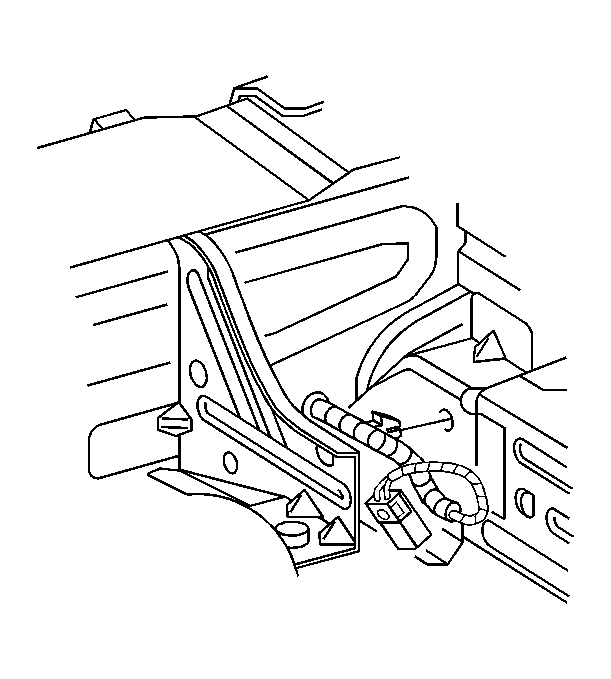 Courtesy of GENERAL MOTORS CORP.
- Remove the wire harness rosebuds from the front right side of the steering column support bracket.
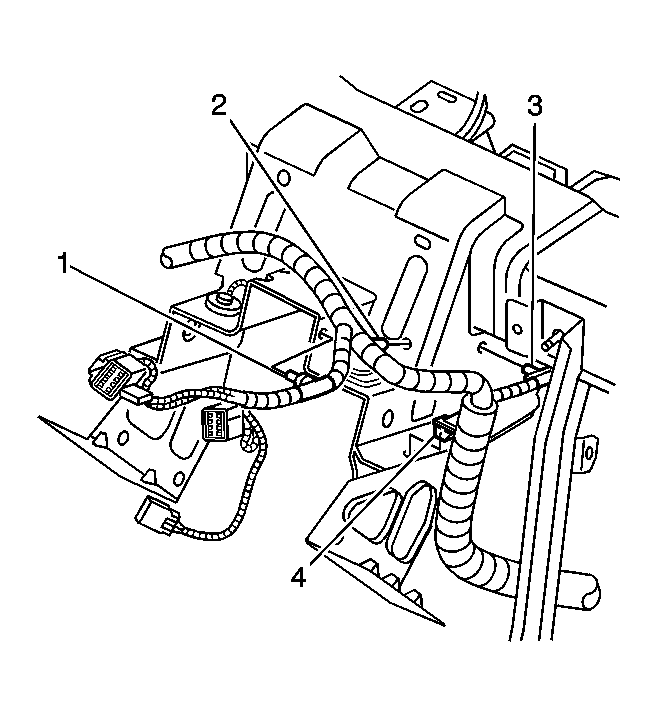 Courtesy of GENERAL MOTORS CORP.
- Remove the wire harness rosebuds (1,2,3,4) from the right side of the steering column support bracket.
 Courtesy of GENERAL MOTORS CORP.
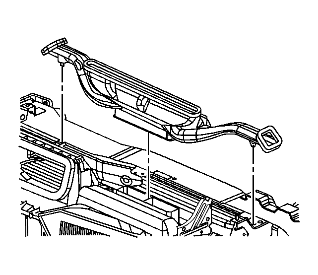
- Unsnap the defroster duct from the HVAC module and the beam. Bend the cluster wire harness tab on the I/P carrier to remove the defroster duct.
 Courtesy of GENERAL MOTORS CORP.
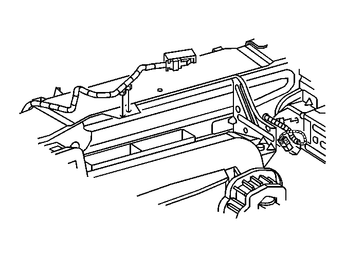
- Remove the cluster wire harness rosebuds from the I/P carrier.
 Courtesy of GENERAL MOTORS CORP.
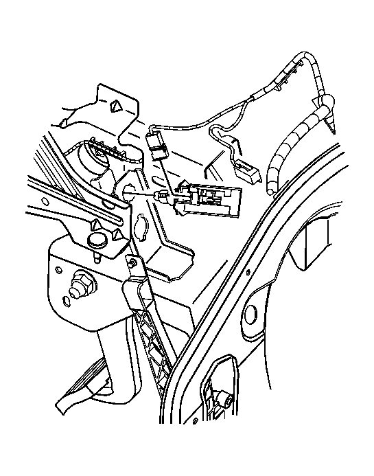
- Remove the stop lamp switch from the brake pedal bracket.
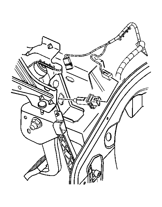 Courtesy of GENERAL MOTORS CORP.
- If equipped with cruise control, remove the cruise control release switch from the brake pedal bracket.
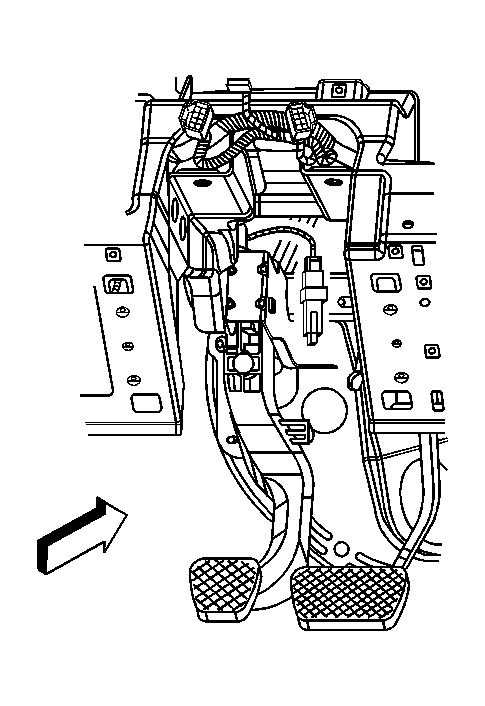 Courtesy of GENERAL MOTORS CORP.
- If equipped with a manual transmission, remove the clutch switch from the clutch pedal bracket.
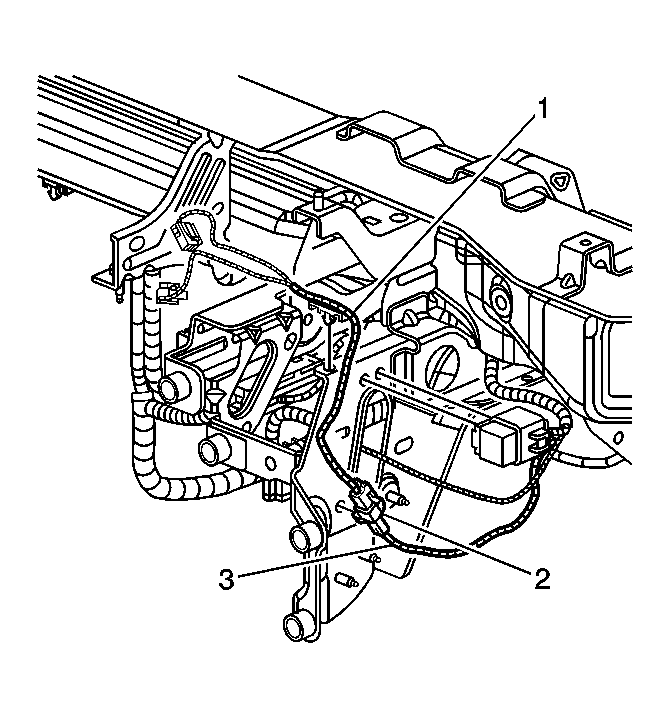 Courtesy of GENERAL MOTORS CORP.
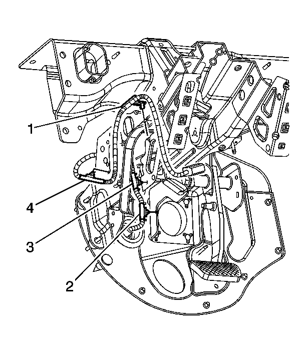
- Remove the wire harness rosebuds (1,2,3) from the front left side of the steering column support bracket.
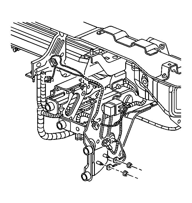 Courtesy of GENERAL MOTORS CORP.
- Remove the I/P wire harness ground wires from the steering column support bracket.
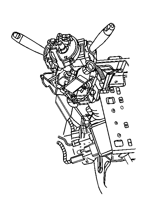 Courtesy of GENERAL MOTORS CORP.
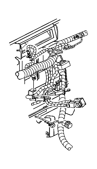
- Disconnect the electrical connectors from the electric power steering motor.
 Courtesy of GENERAL MOTORS CORP.
- Remove the electric power steering power wire rosebuds (1,2,3,4) from the steering column support bracket.
 Courtesy of GENERAL MOTORS CORP.
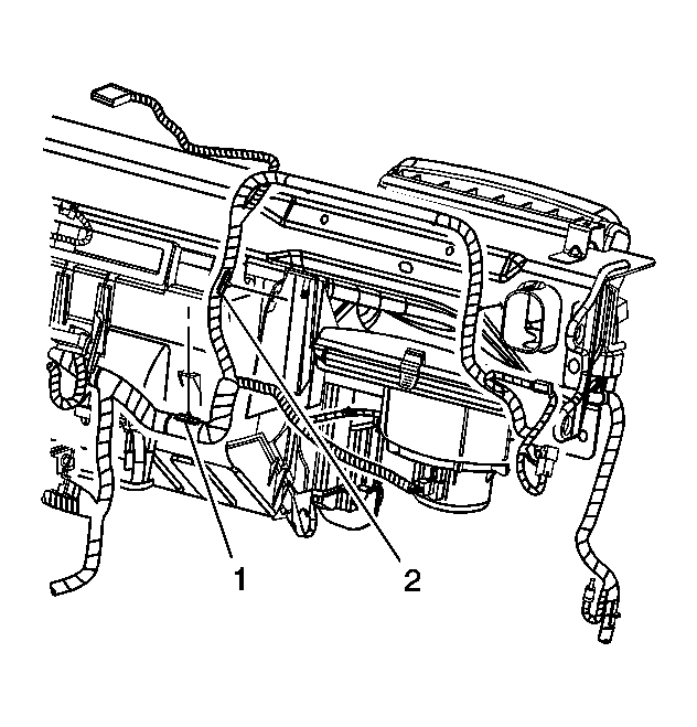
- Remove the wire harness rosebuds from the center of the HVAC module.
 Courtesy of GENERAL MOTORS CORP.
- Remove the wire harness rosebuds (1,2) from the right center of the HVAC module.
 Courtesy of GENERAL MOTORS CORP.
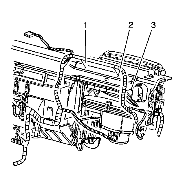
- Remove the wire harness rosebuds (1,2,3) from the right side of the I/P carrier.
 Courtesy of GENERAL MOTORS CORP.
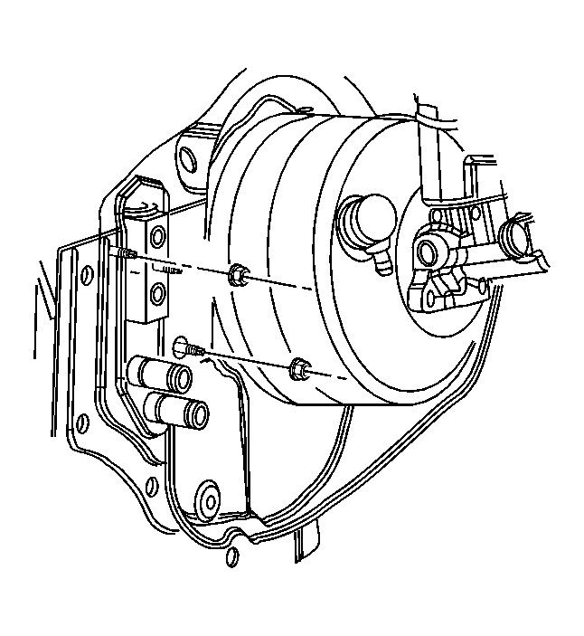
- Remove the HVAC module nuts at the front of dash.
 Courtesy of GENERAL MOTORS CORP.
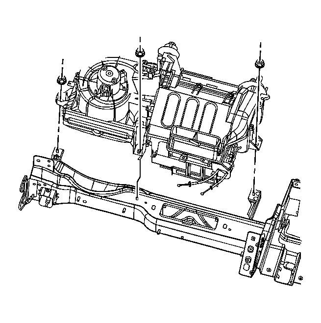
- Remove the HVAC module nuts at the I/P carrier.
 Courtesy of GENERAL MOTORS CORP.
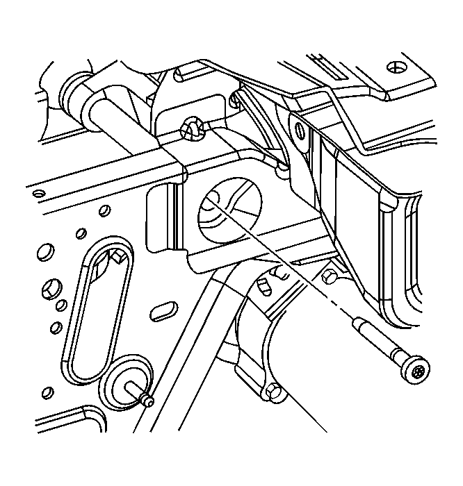
- Remove the steering column pivot bolt and rest the steering column on the floorpan.
 Courtesy of GENERAL MOTORS CORP.
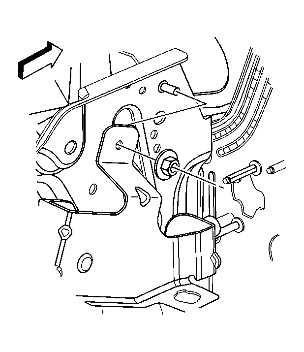
- If equipped with a manual transmission, remove the clutch pedal nut. Position the clutch pedal bracket away from the I/P carrier.
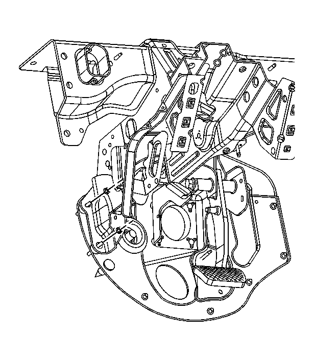 Courtesy of GENERAL MOTORS CORP.
- Remove the left steering column support bracket to front of dash nuts.
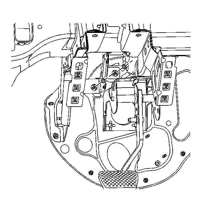 Courtesy of GENERAL MOTORS CORP.
- Remove the center steering column support bracket nuts.
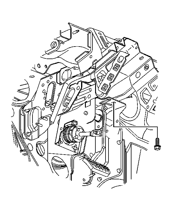 Courtesy of GENERAL MOTORS CORP.
- Remove the brake pedal bracket to steering column support bracket bolt.
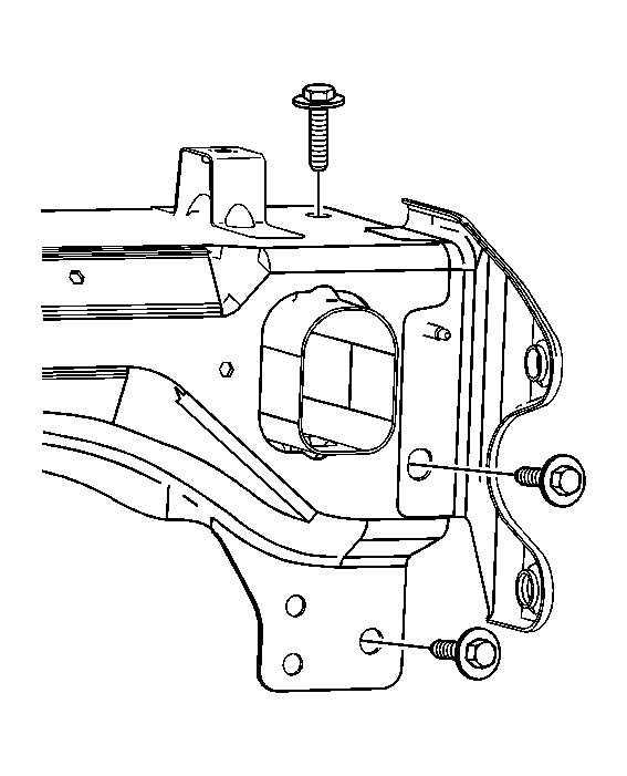 Courtesy of GENERAL MOTORS CORP.
- Remove the right and left I/P carrier to vehicle bolts.
- Slide the I/P carrier rearward, disconnect the HVAC module from the I/P carrier, and remove the I/P carrier from the vehicle.