Diagnostic Procedure
- Connect scan tool to DLC. See COMPONENT LOCATIONS
. Turn ignition on. Using scan tool, command horn relay ON and OFF. If horn relay follows scan tool command, problem is intermittent. See DIAGNOSTIC AIDS
. If horn relay does not follow scan tool command, go to next step.
- Check HORN fuse (10-amp), located in underhood fuse block. If fuse is blown, repair as necessary. If fuse is okay, remove horn relay from underhood fuse block. Connect test light between horn relay cavities No. 28 and 1540. See Fig 1
. Using scan tool, command horn relay ON and OFF. If test light does not illuminate, go to next step. If test light follows scan tool command, check horn relay connector. If connector is okay, replace horn relay. If test light is always illuminated, repair short to ground in Black wire between horn relay and BCM. See WIRING DIAGRAMS
. If Black wire is okay, replace BCM. See appropriate BODY CONTROL MODULES article.
- Connect test light between ground and either horn relay cavity No. 1540. See Fig 1
. If test light illuminates, go to next step. If test light does not illuminate, repair open in battery feed circuit to horn relay. See WIRING DIAGRAMS
.
- Turn ignition off. Disconnect Pink 24-pin BCM connector J3. Using a DVOM, check for voltage between ground and BCM harness connector J3 terminal B2. See Fig 2
. If voltage is not present, repair open or poor connection in Black wire between horn relay and BCM. If voltage is present, check for poor connections at BCM. If connections are okay, replace BCM. See appropriate BODY CONTROL MODULES article.
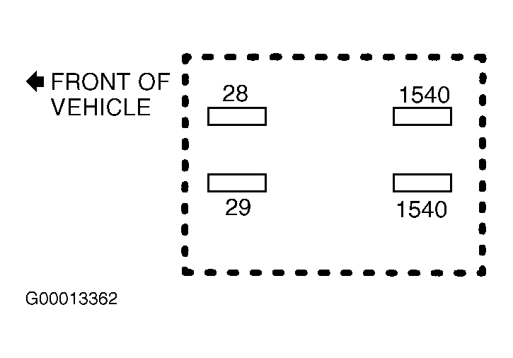 Courtesy of GENERAL MOTORS CORP.
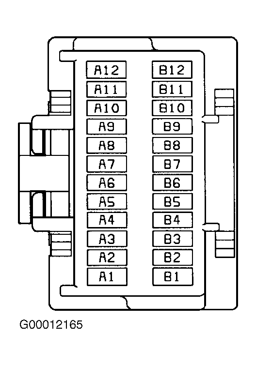 Courtesy of GENERAL MOTORS CORP.