Steering Column Repair
CAUTION: SAFETY PRECAUTIONS MUST BE FOLLOWED WHEN HANDLING A DEPLOYED INFLATOR MODULE (AIR BAG). AFTER DEPLOYMENT, THE INFLATOR MODULE (AIR BAG) SURFACE MAY CONTAIN A SMALL AMOUNT OF SODIUM HYDROXIDE, A BY-PRODUCT OF THE DEPLOYMENT REACTION, THAT IS IRRITATING TO THE SKIN AND EYES. MOST OF THE POWDER ON THE INFLATOR MODULE (AIR BAG) IS HARMLESS. AS A PRECAUTION, WEAR GLOVES AND SAFETY GLASSES WHEN HANDLING A DEPLOYED INFLATOR MODULE (AIR BAG), AND WASH YOUR HANDS WITH MILD SOAP AND WATER AFTERWARDS.CAUTION: WHEN YOU ARE CARRYING AN UNDEPLOYED INFLATOR MODULE:
- DO NOT CARRY THE INFLATOR MODULE BY THE WIRES OR CONNECTOR ON THE INFLATOR MODULE.
- MAKE SURE THE BAG OPENING POINTS AWAY FROM YOU.
WHEN YOU ARE STORING AN UNDEPLOYED INFLATOR MODULE, MAKE SURE THE BAG OPENING POINTS AWAY FROM THE SURFACE ON WHICH THE INFLATOR MODULE RESTS. WHEN YOU ARE STORING A STEERING COLUMN, DO NOT REST THE COLUMN WITH THE BAG OPENING FACING DOWN AND THE COLUMN VERTICAL. PROVIDE FREE SPACE FOR THE AIR BAG TO EXPAND IN CASE OF AN ACCIDENTAL DEPLOYMENT. OTHERWISE, PERSONAL INJURY MAY RESULT.
IMPORTANT: In the event deployment has occurred, inspect coil assembly wire and driver inflator module for any signs of scorching, melting or other damage due to excessive heat. If the coil or inflator module has been damaged, it must be replaced.
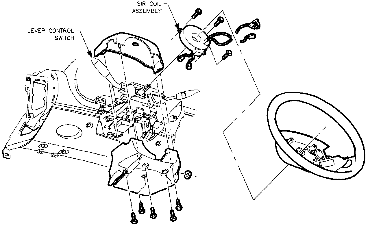
REMOVAL
NOTICE: Cover driver seat to protect seat trim.
1. Disable the SIR system. (Refer to "Air Bag(s) Arming and Disarming.")
2. Remove SIR coil assembly. (Refer to "SIR Coil Assembly Removal.")
IMPORTANT: Protect front of console from being damaged by steering column filler panel.
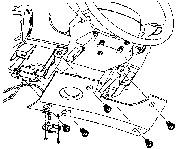
3. Loosen screws holding data link connector near the bottom of steering column filler panel assembly. Remove screws from steering column filler panel. Pull steering column filler panel assembly forward and set down.
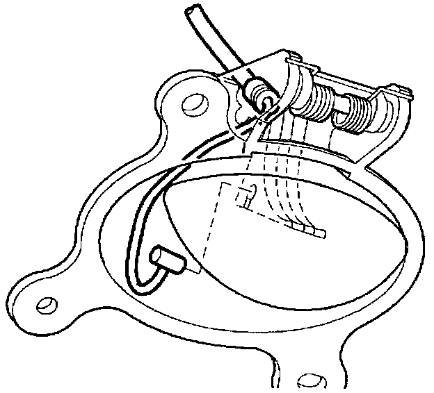
4. Disconnect cable from filler panel. Pull hood release handle forward. Feed cable under hood release handle and slide pin out. Remove steering column filler panel.
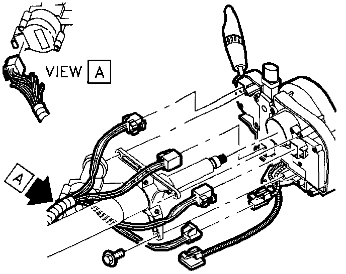
5. Remove connector position assurance (CPA) devices and disconnect connectors from lever combination switch.
6. With SIR system disabled, remove lever combination switch.
7. Disconnect connection from ignition switch.
8. On vehicles equipped with an automatic Transaxle, disconnect park lock cable from ignition module assembly.
IMPORTANT: The park lock cable is located at the front side of the ignition module assembly.
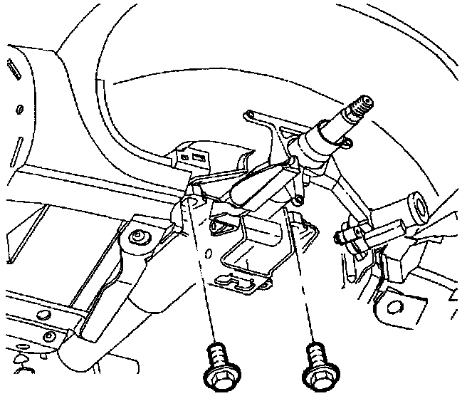
9. Remove upper steering column bolts. Rest steering column on front seat.
10. Remove bolt from intermediate shaft and disconnect shaft from column.
11. Remove steering column from vehicle.
12. Position steering column in a vise at the upper bracket. Using a center punch, mark the center of the shear bolts on ignition module assembly.
13. Drill a small hole (1/8 in. drill bit) in the shear bolts at the center mark. Remove the shear bolts with a screw extractor, and remove the ignition module assembly from the column.
INSTALLATION

1. Use new shear bolts to install ignition module assembly on steering column. Torque shear bolts until heads break off.
IMPORTANT: Install with key out to use lock pin to locate on steering column. Rotate column to ensure engagement of lock pin in column.
2. Install steering column at hinge point.
3. Connect intermediate shaft, install bolt.
Torque: 47 N.m (34 ft-lbs.)
4. Torque lower steering column support bracket bolts and nuts.
Torque: 25 N.m (19 ft-lbs.)
5. Install upper steering column bolts.
Torque: 35 N.m (26 ft-lbs.)
6. Connect ignition switch to electrical connector.
7. Install lever combination switch by fitting into bottom locating holes on ignition module.
8. Install connectors to lever combination switch and install connector position assurance (CPA) devices.
9. Install lower and upper steering column shrouds.
10. Install ignition lock cylinder.
11. Pull hood release handle forward. Feed cable under hood release handle and slide pin in. Connect cable to filler panel.
12. Install steering column filler panel assembly. Tighten screws which hold the data link connector.
13. Install SIR coil assembly. (Refer to "SIR Coil Assembly Installation.")
14. Enable SIR system. (Refer to "Air Bag(s) Arming and Disarming.")