Fuel Rail: Service and Repair
WARNING: do not allow smoking or the use of open flames in the area where work on the fuel system is taking place. Anytime the fuel system is being worked on, disconnect the negative battery cable, except for those tests where battery voltage is required.NOTE: When servicing the fuel rail assembly, be careful to prevent dirt and other contaminants from entering the fuel passages. Fittings should be capped and holes plugged during servicing. Before removal, the fuel rail may be cleaned with a spray type engine cleaner, AC Delco X-30A or equivalent, following package instructions. Do not soak rails in cleaning solvent.
FUEL RAIL ASSEMBLY REMOVAL
1. Disconnect negative battery terminal.
2. Remove air intake tube, air filter cover and fresh air tube.
WARNING: Whenever fuel line fittings are loosened or disconnected, wrap a shop cloth around fitting while connecting gauge, to collect fuel place cloth in an approved container.
Fuel System Pressure Relief:
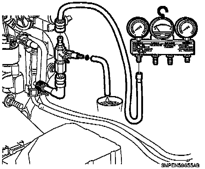
3. Connect fuel gage bar kit (Saturn Tool) SA9127E to fuel pressure test port. Use 90° adaptor SA9403E.
4. Install bleed hose into an approved container and open valve to bleed system pressure. Once pressure is bled, remove gauge from fuel pressure test port and recap test port.
Fuel Line Retainer:
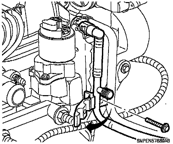
5. Remove the bolt at the fuel line clip below the fuel pressure test port. Open the hinged clip and separate the fuel supply line and the fuel return line from the clip.
NOTE: Failure to open the clip could result in kinking of the fuel lines when connections at the fuel rail are disconnected.
WARNING: Whenever fuel line fittings are loosened or disconnected, wrap a shop cloth around fitting while connecting gauge, to collect fuel place cloth in an approved container.
Disconnecting Fuel Line:
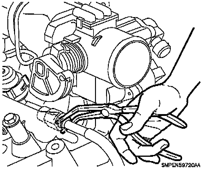
6. Disconnect the fuel return line by compressing the two plastic retainer tabs together and pulling on the fuel return line. Access to the tabs can be achieved by using a right-angled needle nose pliers. Remove and discard the plastic retainer.
7. Disconnect the fuel supply line by compressing the two plastic retainer tabs and pulling on the fuel supply line. Remove and discard the plastic retainer.
8. Remove throttle control cable bracket bolts. Disconnect cable from throttle lever and lay over intake manifold.
9. Disconnect vacuum line at pressure regulator.
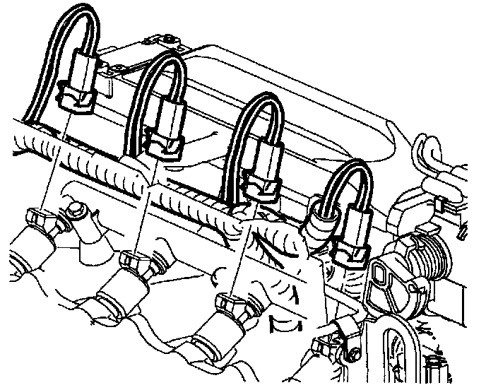
10. Disconnect injector electrical connectors.
Fuel Rail Attaching Bolts:
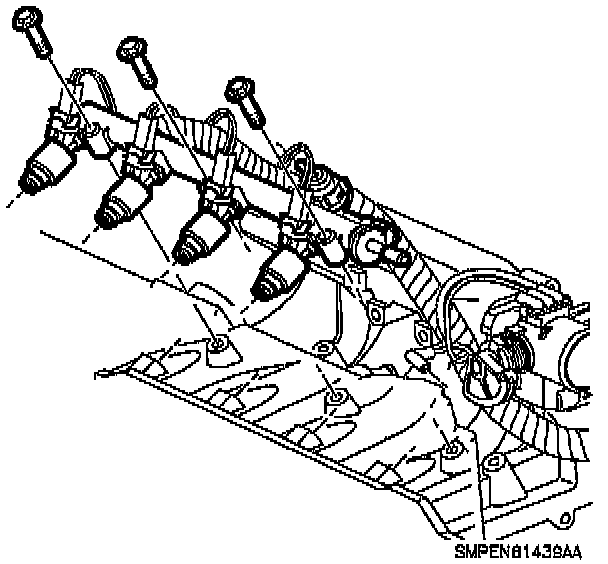
11. Remove fuel rail assembly attachment bolts.
NOTE: Use care in removing fuel rail assembly to prevent damage to the electrical connector terminals and spray tips. The fuel injector is serviced as a complete assembly only. Since it is electrical, it should not be immersed in any cleaner.
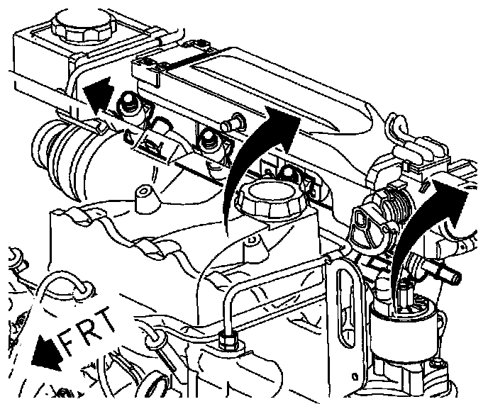
Areas Of Possible Contact:
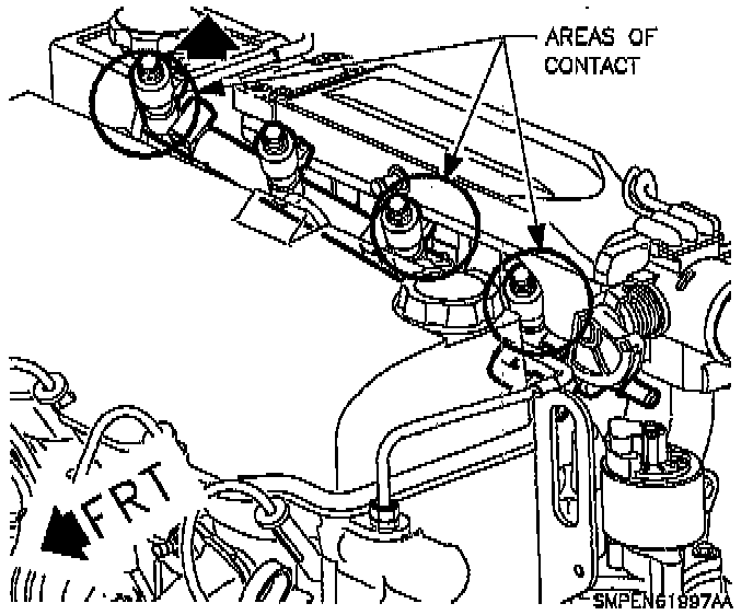
12. Remove fuel rail assembly.
NOTE: Enough space exists between the intake manifold and cam cover to remove the fuel rail as an assembly.
a. Carefully pull rail back and upward to remove injectors from the intake manifold ports.
b. Move rail back against intake manifold runners.
c. Rotate rail so injectors point upward.
d. Move the rail against the power steering pump.
e. Lift the #1 injector and remove the rail from between the cylinder head and intake manifold.
NOTE: Whenever the fuel rail is removed for service, the injectors must be removed and upper and lower injector 0-rings must be replaced.
Fuel Injector Retainer And O-ring:
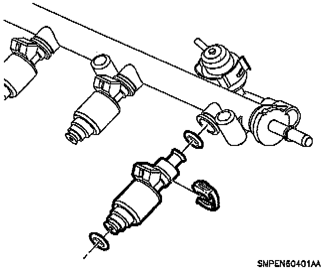
13. Remove clips retaining the fuel injectors and pull injectors out of the rail.
14. Disassemble the injector 0-ring seals using a special seal removal tool or brass seal pick from each injector and discard.
NOTE: When cleaning or servicing the fuel rail, care must be taken to assure that the plastic fuel rail surfaces that mate to the injector 0-rings are not scratched.
Areas Of Possible Contact:
15. Lubricate the new 0-ring seals with clean engine oil and install injectors into fuel rail.
INSTALLATION
NOTE: Lubricate 0-rings at injector tips prior to installing injectors into intake manifold.
1. To install fuel rail assembly to intake manifold:
a. With injectors pointing upward, lower the fuel rail into the cavity between the cam cover and intake manifold.
b. Move rail towards power steering pump.
c. Rotate the injectors into a horizontal position. The fuel rail must be placed against the intake manifold runners to accomplish this.
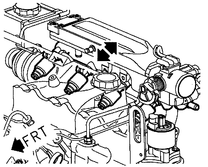
d. Align injectors with their respective port holes.
e. Carefully push fuel injectors into holes, making sure they have seated on intake manifold.
Fuel Rail Attaching Bolts:
2. Install fuel rail attaching bolts.
Torque to 10 N.m (89 in-lbs)
3. Connect fuel injector electrical connectors. Push in until a click is heard and pull back to insure engagement.
Positioning Regulator On Fuel Rail:
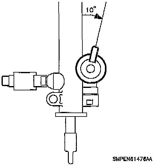
NOTE: Position the fuel pressure regulator tube at a 10 degree angle to the fuel rail body.
4. Connect PCV valve hose and connect vacuum line to fuel pressure regulator. Make sure they are fully seated.
WARNING: lubricate with clean engine oil the male end of the fuel rail that connects with the fuel supply line. Firmly press on female coupler until a click is heard, then pull back to confirm engagement pinched, kinked or damaged fuel lines must be replaced.
NOTE: Replace plastic fuel line retainers whenever the fuel supply or return line is disconnected at the fuel rail. Install the new retainer into the female cavity of the connection. Care must be taken to assure that the locking tab is centered in the window of the female cavity Firmly press the female connection onto the male end until a click is heard, then pull back to confirm engagement. Pinched, kinked, or damaged fuel lines must be replaced.
NOTE: The service retainers are different in color from the original equipment retainers. The service retainers are clear.
5. Lubricate with clean engine oil the male fuel feed line and the male fuel return line connections. Attach the fuel feed line and pull back to confirm engagement. Attach the fuel return line and pull back to confirm engagement.
6. Install fuel line clip to bracket.
Torque to 7 N.m (62 in-lbs)
7. Connect negative battery terminal.
8. Prime fuel system.
a. Turn ignition on for 5 seconds and then off for 10 seconds.
b. Repeat step 9a twice.
c. Crank engine until it starts (maximum starter motor cranking time is 20 seconds).
d. If engine does not start, repeat steps 9a-9c.
9. With engine off and ignition on, pressurize the fuel system and check for leaks.
10. Install intake tube and air filter cover.