Removal
NOTE: Failure to use the anti-static mat SA 9502Z properly will result in damage or latent damage to the cluster electronics.IMPORTANT:
^ If the lens/mask gets dirty it can be cleaned by following the procedures in this manual. If a dial face gets dirty it can be cleaned by using glass cleaner and a lint free rag.
^ Do not touch or bump the pointers of the gages. If the pointers are moved from their positions the calibration of the gage will be affected, and the gage will no longer be accurate and must be replaced.
1. Remove instrument panel cluster assembly.
2. Thoroughly clean hands with soap and water to remove any oil or other substances which could damage the cluster. If unable to clean hands, an alternative is to wear surgical gloves during all procedures.
IMPORTANT: It is strongly recommended that rubber gloves (e.g., like surgical gloves) be worn while performing removal and installation procedures to prevent grease, smudges, scratches and fingerprints.
3. Place anti-static mat SA 9502Z down on the work area. In order to ground the mat connect the alligator clip to a large metal object (i.e. work bench) mating sure that the attaching point is a bare metal surface and not painted or coated. Also put the wrist strap around one of your wrists.
4. Place a clean, dry, soft material such as a cloth baby diaper on top of the anti-static mat.
5. Place instrument panel cluster assembly face down on the cloth and the anti-static mat.
Coolant Temperature Gage Removal:
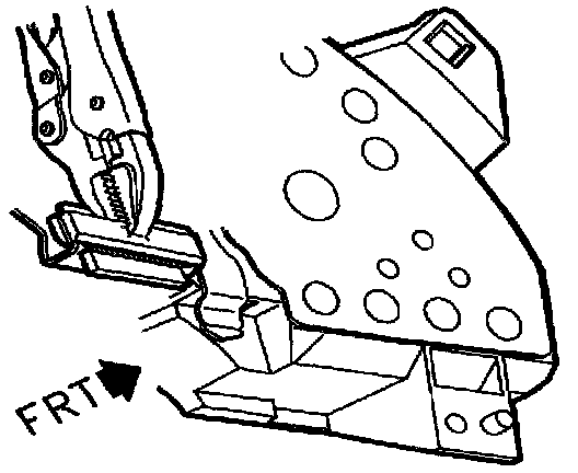
6. Insert the curved jaw of the tool, SA9701Z, under the speedometer flex printed circuit board connection.
7. Position and close the vise grips so that the paddles, welded to laws, cover the exposed crimps (corning through copper traces).
8. Gently pull away from the cluster in a direction parallel to the back surface of the cluster.
Coolant Temperature Gage Removal:
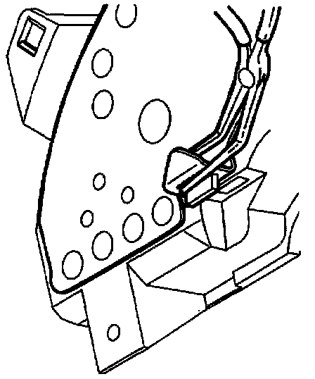
9. Using SA 9507Z remove flex printed circuit board (PCB) tabs from location tab under tachometer.
10. With SA 9507Z grasp across terminals on both sides of the flex PCB.
11. Gently pull connector straight out from housing.
Coolant Temperature Gage Removal:
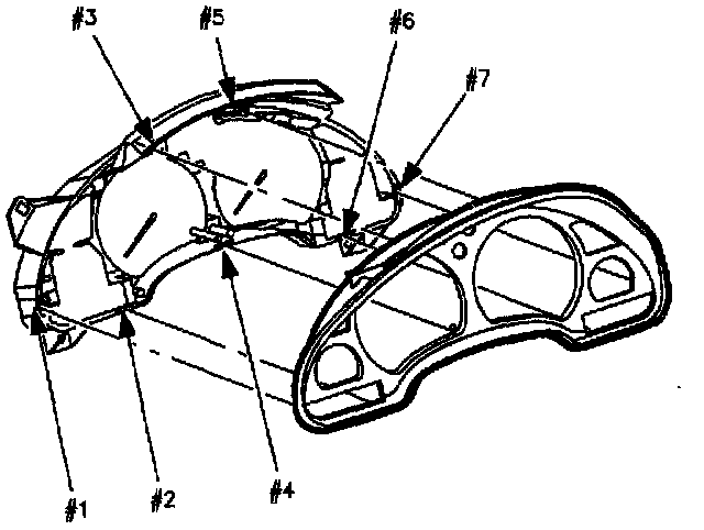
12. With end of housing (white portion of cluster) in one hand and lens/mask assembly (black portion of cluster) in other hand, disengage clip #1 with one hand while separating lens/mask assembly from housing with other hand.
13. Repeat for clips #2 through #7.
14. Place lens/mask assembly in clean area.
IMPORTANT: Do not touch inside of lens.
Coolant Temperature Gage Removal:
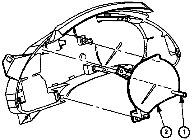
5. Insert SA 9504Z cluster gage removal tool straight down into the bottom clip (below mph, km/h text) until you hear clip release. Then, pull straight up on reset knob.
16. Reset knob may pull up and "click" while removing speedometer. After speedometer is removed, push reset knob in to re-engage.
Coolant Temperature Gage Removal:
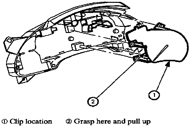
17. Insert SA 9504Z cluster gage removal tool straight down into the bottom clip slot (below RPM text) until you hear clip release, then grasping gage with left hand (next to 1000 RPM mark) gently pull straight up.
Coolant Temperature Gage Removal:
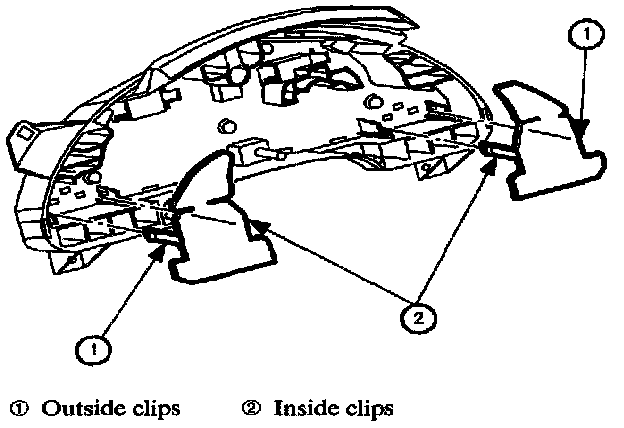
18. With your thumb on the inside clip and a finger on the outside clip, gently squeeze in on both clips and pull the coolant temperature gage straight up to remove.