Drive Belt Tensioner: Service and Repair
WARNING: The tensioner assembly's internal parts are not serviceable. to avoid injury, do not disassemble tensioner.REMOVAL
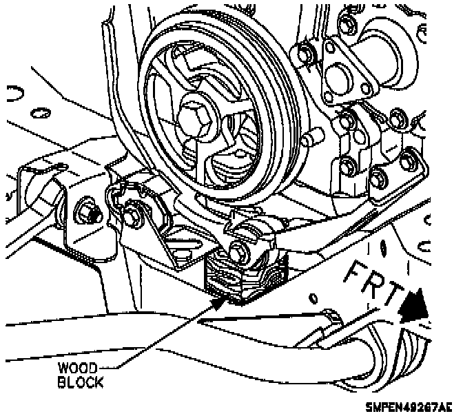
1. The right-hand upper engine mount and lower splash shield clips require removal for tensioner and idler pulley fastener access. A 1 inch x 1 inch x 2 inch long block of wood can be placed between the torque strut and cradle to support engine during mount removal.
NOTE: Installation of the wood block prior to removing the upper engine torque axis mount allows the mount to be easily installed without lifting or jacking the powertrain.
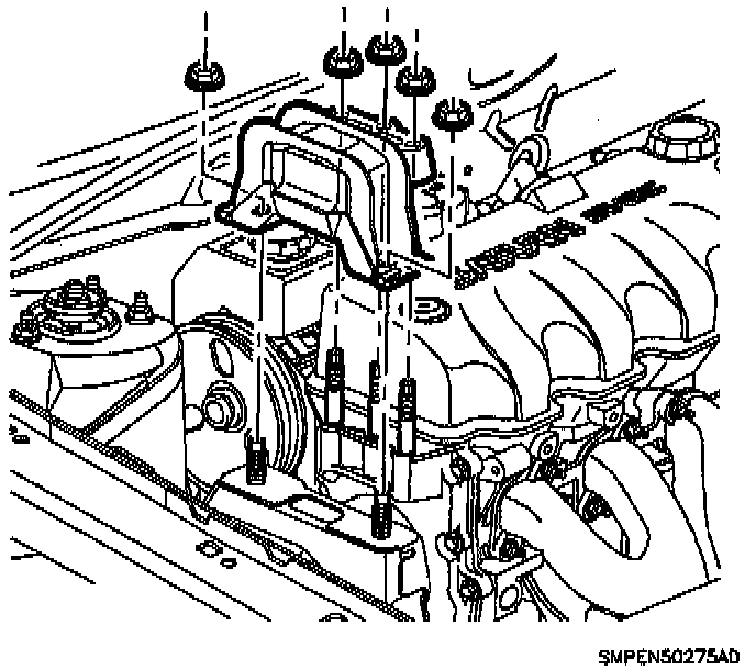
2. Remove the three engine, upper engine torque axis mount-to-front cover nuts and the two engine mount-to-midrail bracket nuts, allowing the powertrain to rest on the block of wood.
3. Remove accessory drive belt.
NOTE: Depending on position of engine to right-hand midrails, the tensioner can possibly be removed without power steering pump removal.
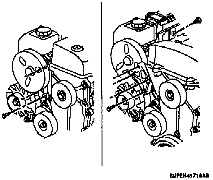
4. Remove power steering pump assembly with bracket. See Steering and Suspension.
NOTE: Access and removal of the tensioner can also be completed by removing the right-hand tire and splash shield.
5. Remove upper and lower tensioner attachment fasteners.
6. Remove tensioner assembly.
CAUTION: The engine may have to be moved slightly toward the left-hand fender for tensioner removal. A pry bar can be placed between the steel engine motor mount and frame rail to move the engine. Do not pry against aluminum engine components or accessories.
INSTALLATION
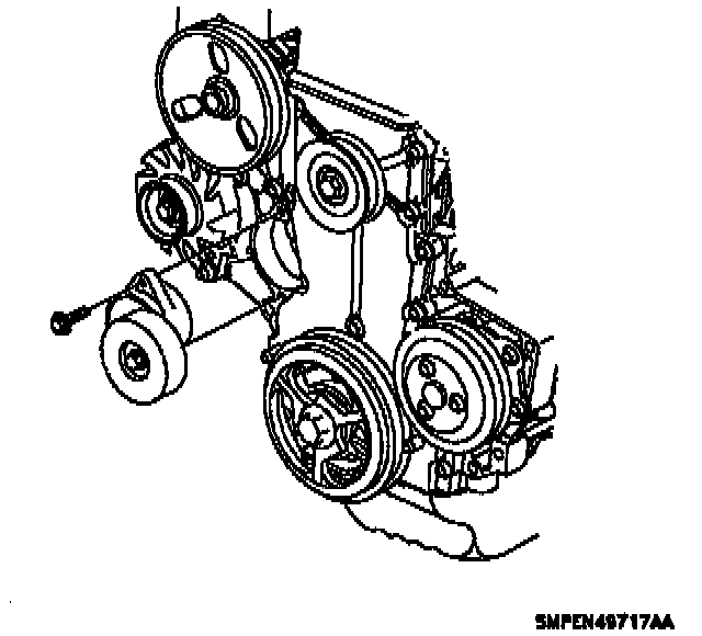
1. Install tensioner and attachment fasteners. Torque to 30 N.m (22 lb ft).
CAUTION: The accessory drive belt tensioner can be installed at two different positions. Correct installation of the accessory drive belt tensioner positions the pulley at approximately the 3 o'clock position.
2. Install the power steering pump assembly. See Steering and Suspension.
3. Install the accessory drive belt. Make sure the belt is properly aligned on the pulleys.
CAUTION: To prevent [1][2]engine front cover and mount damage, the three front engine mount-to-front cover nuts must be tightened down uniformly.
4. Install the engine mount-to-midrail bracket nuts first. Next, install the three engine mount-to-front cover nuts. Remove the block of wood from under the torque strut after the engine mount assembly is installed. Tighten engine mount-to-front cover to 50 N.m (37 lb ft). Tighten engine mount-to-midrail bracket to 50 N.m (37 lb ft).
5. Attach the lower splash shield clips.