Ignition System ("J" & "L" Bodies)
- Disconnect tachometer wire if equipped. A shorted tachometer or tachometer circuit will prevent vehicle from starting.
- Install scan tester. Check for stored ECM trouble codes. Scan TPS voltage. If TPS reading is greater than 2.5 volts, use Code 21 chart first. Scan RPM while cranking engine. If RPM is displayed on scan tester, go to step 5). If RPM is not displayed, check for spark on 2 wires (2-4 or 4-6) using Spark Tester (ST-125). Check one wire at a time. Leave other wires connected to plugs while cranking. If spark occurs on both wires, go to next step. If no spark occurs on either wire, go to step 11). If spark occurs on one wire only, go to step 4).
- Turn ignition off. Disconnect 6-wire ignition module connector. Turn ignition on. Monitor scanned RPM while momentarily touching RPM reference circuit wire (circuit No. 430) of ignition module harness connector with a test light connected to battery voltage. If RPM is indicated on scan tester, problem is faulty ignition module-to-harness connection or faulty DIS ignition module. If RPM is not indicated, problem is open or short to ground in RPM reference circuit or faulty ECM.
- If spark occurs on one wire only, check pair of wires for plug that did not spark. Each wire should measure less than 30,000 ohms resistance. If wires are okay, switch coil assemblies. If problem moves with coil, replace faulty coil. If problem does not follow coil, ignition module is faulty.
- Scan fuel pump signal (PPSW) during cranking. If voltage is not indicated, see Code 54 chart in appropriate TESTS W/CODES
article in the ENGINE PERFORMANCE Section. If voltage is indicated, check for spark on 2 wires (2-4 or 4-6) using Spark Tester (ST-125). Check one wire at a time. Leave other wires connected to plugs while cranking. If spark occurs on both wires, go to step 6). If spark does not occur on either wire, ignition module is faulty. If spark occurs on one wire, go to step 4).
- If spark occurs on both wires, remove Blue and Green wire injector harness connectors. While cranking engine, probe each connector (ECM side) with test light connected to battery voltage. If both connectors do not cause test light to flash, go to next step. If both connectors cause test light to flash, recheck fuel system pressure. If fuel pressure is within specification, fuel injection system is okay. See HARD START symptom in TESTS W/O CODES
article in the ENGINE PERFORMANCE Section.
- If test light connected to injector harness connectors did not flash (no light), go to next step. If test light connected to either injector harness connectors is on steady, check injector drive circuit with steady light for short to ground. If circuit is not shorted to ground, ensure injector resistance is greater than 8 ohms (but not infinity). Replace any injector with less than 8 ohms resistance. If injectors are okay, ECM is faulty.
- Turn ignition on. Probe injector harness terminals (injector side) with test light connected to ground. If test light is on at both terminals, go to next step. If light is off at both terminals, repair open in injector power supply circuit. Since injectors are wired in parallel, if light is on at one terminal only, problem is in harness which did not light.
- Reconnect both injector harness connectors. Turn ignition off. Disconnect ECM connectors. Turn ignition on. Probe ECM harness terminals BC11 and BC12 using test light connected to ground. See Fig 1
or Fig 2
. If test light is off, repair open in circuit which did not light. If test light is on at both terminals, turn ignition off. Disconnect all injector connectors. Turn ignition on. Probe Blue and Green wires (ECM side of injector harness) using test light connected to ground. If test light is off, go to next step. If test light is on, repair short to voltage in that circuit.
- Check resistance between injector harness terminals "A" and "C", "A" and "D", "B" and "D" and "B" and "C". If resistance is less than 4 ohms, check harness wires for short to each other and check individual injector resistance with injector connectors removed. Resistance should be 8 ohms or more (but not open). If no short to voltage is found, no injector harness wires are shorted together and no injector has improper resistance, replace ECM.
- If no spark is present and RPM is not indicated on scan tester, as determined in step 2), turn ignition off. Disconnect 2-wire connector at ignition module. Turn ignition on. Connect test light across harness connector terminals. If test light is on, go to step 13). If test light is off, probe terminal "B" of harness connector with test light connected to ground.
- If test light is off, repair open in ignition module power feed circuit. If test light is on, repair open in ignition module ground circuit wire between terminal "A" and engine ground.
- Disconnect crankshaft sensor 3-wire connector at ignition module. Using ohmmeter, check resistance between Purple and Yellow wires of 3-wire harness connector. If resistance is 900-1200 ohms, go to next step. If resistance is less than 900 ohms, crankshaft sensor leads are shorted together or crankshaft sensor is faulty. If resistance is greater than 1200 ohms, repair open in Purple or Yellow wire between harness connector and crankshaft sensor or replace faulty crankshaft sensor.
- Set voltmeter on 2-volt AC position. Crank engine with voltmeter leads connected between Purple and Yellow wires of crankshaft sensor harness. If voltmeter reading is not greater than .1 volt, problem is faulty connection at crankshaft sensor or faulty sensor. If voltmeter reading is greater than .1 volt, replace DIS ignition module.
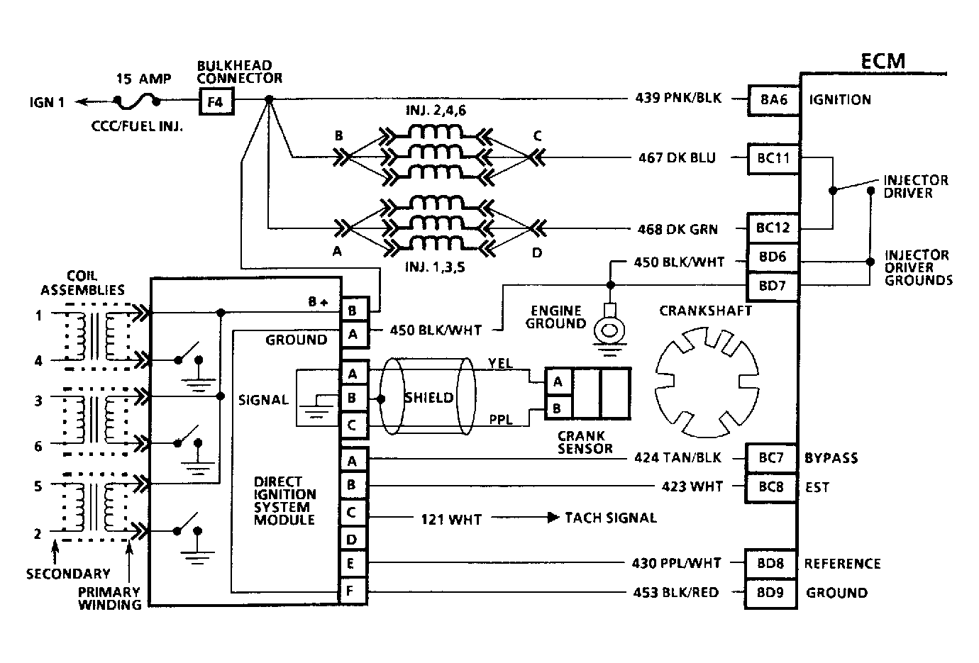 Courtesy of GENERAL MOTORS CORP.
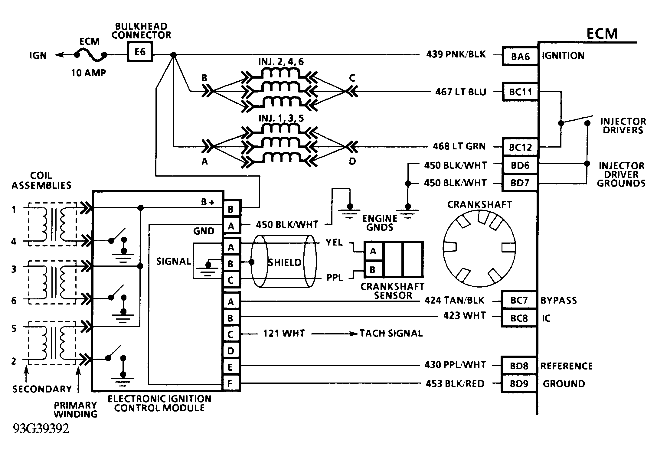 Courtesy of GENERAL MOTORS CORP.