Component Overview
WARNING: This page does not describe the selected car, but rather 8 other vehicles, including the 2018 Porsche Cayenne, 2017 Porsche Cayenne, 2016 Porsche Cayenne, 2015 Porsche Cayenne, and 2014 Porsche Cayenne. However, it is still accessible from the selected car via links, so may be relevant.
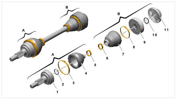 Courtesy of PORSCHE CARS NORTH AMERICA, INC.
| No. |
Designation |
Qty. |
Removal |
Installation |
| A |
Outer joint |
|
|
|
| 1 |
Joint pin |
1 |
Tap joint pin out of drive shaft using a hammer and mandrel. |
Use a hammer to fit the joint pin as far as it will go on to the drive shaft. |
| 2 |
Circlip, 21 x 1.7 |
1 |
Remove circlip. |
Do not confuse circlip no. 2 with circlip no. 10 on inner joint. The two parts are not identical. Ensure that the circlip is seated correctly. |
| 3 |
Hose clamp, 82 x 10 |
1 |
Remove hose clamp using a hammer and chisel, for example. Do not damage boot. |
Fit hose clamp with boot on the joint pin. |
| 4 |
Boot |
1 |
Remove boot from the shaft. |
Do not confuse boot no. 4 with boot no. 7. The two parts are not identical. Position boot correctly. |
| 5 |
Hose clamp, 28.5 x 10 |
1 |
Remove hose clamp using a hammer and chisel, for example. Do not damage boot. |
For securing the boot. |
| B |
Inner joint |
|
|
|
| 6 |
Hose clamp, 32 x 10 |
1 |
Remove hose clamp using a hammer and chisel, for example. Do not damage boot. |
For securing the boot. |
| 7 |
Boot (with bellow support) |
1 |
Remove boot from the shaft. |
Do not confuse boot no. 7 with boot no. 4. The two parts are not identical. Ensure correct seating. |
| 8 |
Bellow support (with boot) |
1 |
Remove bellow support. |
Use two cheese-head bolts to center the bellow support. Fit at the correct position and seal the sealing faces with special sealant
. |
| 9 |
Joint |
1 |
Press joint off the drive shaft. |
Using a hammer and mandrel, drive the joint as far as it will go onto the drive shaft. |
| 10 |
Circlip, 25 x 1.2 |
1 |
Remove circlip carefully with a pliers. |
Do not confuse circlip no. 10 with circlip no. 2 on outer joint. The two parts are not identical. Ensure that the circlip is seated correctly. |
| 11 |
Lid |
1 |
Remove cap. |
Use two cheese-head bolts to center the cap. Ensure correct seating. Seal the sealing faces with special sealant
. |