Installing Wire Harness For Engine
 Courtesy of PORSCHE CARS NORTH AMERICA, INC.
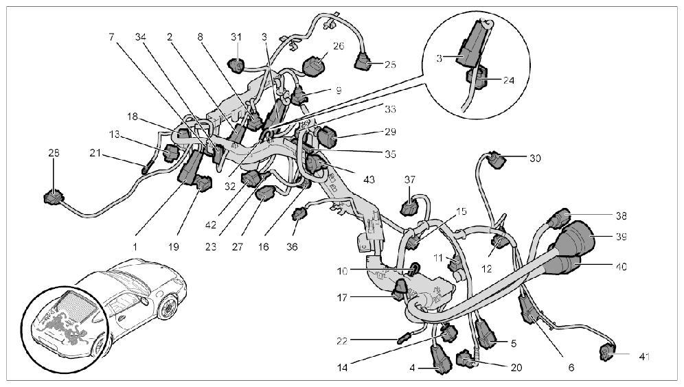
- 01 - 03
- Ignition coil on cylinder bank 1 - 3
- 04 - 06
- Ignition coil on cylinder bank 4 - 6
- 07 - 09
- Fuel injector 1 - 3
- 10 - 12
- Fuel injector 4 - 6
- 13 - 14
- Camshaft sensor
- 15 - 16
- Knock sensor
- 17 - 18
- Camshaft adjuster
- 19 - 20
- Valve lift adjuster
- 21 - 22
- Ground
- 23
- Generator terminal 30
- 24
- Speed sender
- 25
- Ambient air valve
- 26
- Secondary air blower
- 27
- Generator
- 28
- Exhaust temperature sensor
- 29
- Throttle valve
- 30
- Oil-level sensor
- 31
- Tank vent
- 32
- Water temperature sensor
- 33
- Water pump
- 34
- Starter terminal 50
- 35
- Air-conditioning compressor
- 36
- Engine compartment temperature
- 37
- Oil-pressure sender with temperature sensor
- 38 - 40
- Engine/rear end connection point
- 41 - 42
- VTG adjuster
- 43
- Boost-pressure sensor
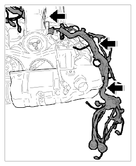
- Slide engine wire harness onto the engine from the right and position it.
 Courtesy of PORSCHE CARS NORTH AMERICA, INC.
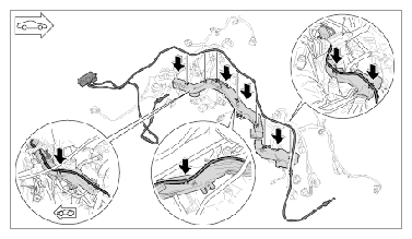
- Lay line for exhaust temperature sensor on the cable duct for the engine wire harness and clip it in.
 Courtesy of PORSCHE CARS NORTH AMERICA, INC.
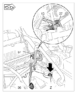
- Screw in fastening screw for cable duct and connect connectors.
 Courtesy of PORSCHE CARS NORTH AMERICA, INC.
- 3.1. Insert connectors -15, 37-
one after the other until the connectors engage securely.
- 3.2. Screw in fastening screw -Z-
for the cable duct. → Tightening torque: 10 Nm (7.5 ft. lb.)
- Insert connector for the knock sensor -16-
until the connector engages securely.
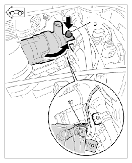 Courtesy of PORSCHE CARS NORTH AMERICA, INC.
- 4.1. Position the water pump and secure it with the fastening screw -B-
.
- Screw in fastening screw for cable duct and connect connectors.
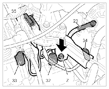 Courtesy of PORSCHE CARS NORTH AMERICA, INC.
- 5.1. Insert connectors -33, 32, 34-
one after the other until the connectors engage securely.
- 5.2. Screw in fastening screw -Z-
for the cable duct. → Tightening torque: 10 Nm (7.5 ft. lb.)
- Clip in cable duct -X2-
on the fuel gallery.
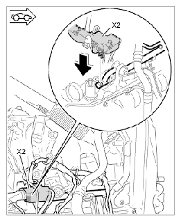 Courtesy of PORSCHE CARS NORTH AMERICA, INC.
- Clip wire harness in at two places on the fuel gallery 4 - 6.
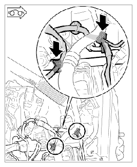 Courtesy of PORSCHE CARS NORTH AMERICA, INC.
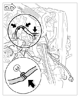
- Clip in wire harness at two places on the oil-fill pipe holder and at one place on the intake pipe.
 Courtesy of PORSCHE CARS NORTH AMERICA, INC.
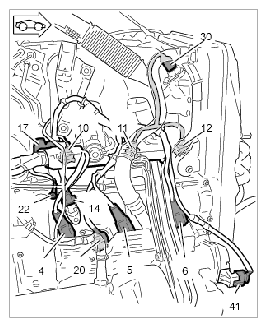
- Connect connectors for engine wire harness on the right side until the connectors engage securely.
 Courtesy of PORSCHE CARS NORTH AMERICA, INC.
- 9.1. Connect connectors -30, 17, 10, 11, 12, 4, 14, 20, 5, 6, 41-
one after the other until they engage securely.
- 9.2. Position ground connection -22-
on the engine housing and secure with the fastening screw. → Tightening torque: 10 Nm (7.5 ft. lb.)
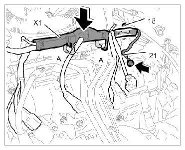
- Install connector, ground strap for cylinder 1 - 3 and the cable duct.
 Courtesy of PORSCHE CARS NORTH AMERICA, INC.
- 10.1. Connect connector -18-
until it engages securely.
- 10.2. Position ground connection -21-
on engine housing and secure with the fastening screw. → Tightening torque: 10 Nm (7.5 ft. lb.)
- 10.3. Clip in cable duct -X1-
on the fuel gallery 1 - 3.
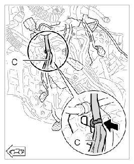
- Clip branch of line -C-
to speed sender into the holder.
 Courtesy of PORSCHE CARS NORTH AMERICA, INC.
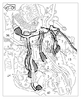
- Connect connectors for engine wire harness on the left side - cylinder 4 - 6 - until they engage securely.
 Courtesy of PORSCHE CARS NORTH AMERICA, INC.
- 12.1. Connect connectors -7, 8, 9, 13, 19, 1, 2, 3, 24, 42-
one after the other until they engage securely.
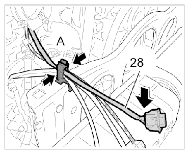
- Lay line for exhaust temperature sensor -28-
into the retaining clip -A-
and close the clip.
 Courtesy of PORSCHE CARS NORTH AMERICA, INC.