Installing Camshafts - Cylinder Bank 4 - 6
- In order to remove the play from the control chain drive, turn the engine at the belt pulley of the crankshaft clockwise (engine direction of rotation) to 60° before TDC (identification U6 on the belt pulley is flush with the fixing bore in the crankcase). See Fig 1. Fix with special tool (fixing pins) 9595/1, use short fixing pin.
 Courtesy of PORSCHE OF NORTH AMERICA, INC.
- Turn the engine at the assembly support until cylinder bank 4 - 6 stands vertically upwards.
- Oil the bearing surfaces of the camshafts with new engine oil.
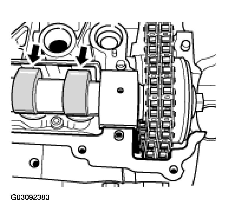
- Insert inlet camshaft 4 - 6. If necessary, pre-assemble the inlet camshaft. See DISASSEMBLING AND ASSEMBLING INLET CAMSHAFT - AS OF MY 2003 . Pull the control chain out of the chain housing of the cylinder head, for example, with a welding wire, and position on the toothed ring of the camshaft adjuster, at the same time inserting the camshaft at overlapping TDC of cylinder 4 -arrows- (the cams of cylinder 4 point towards the bulkhead of the flat-base tappet housing). See Fig 2.
 Courtesy of PORSCHE OF NORTH AMERICA, INC.
NOTE:
- Make sure that the bearing sleeve of the inlet camshaft is positioned correctly.
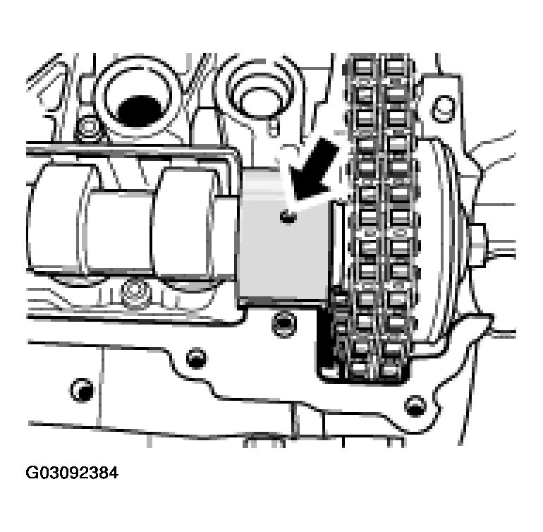
- The bearing sleeve of the inlet camshaft must be positioned so that the centrally bored blind hole points vertically upwards -arrow-
(the rib of the cylinder head should also be at the Centre in relation to the bearing sleeve). See Fig 3. In this position, the dowel pin in the bearing bore of the cylinder head will fit precisely into the opposite off-centre blind hole bore. Any other bores are through-holes for guiding the oil.
 Courtesy of PORSCHE OF NORTH AMERICA, INC.
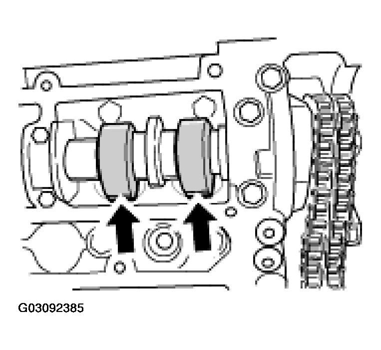
- Insert exhaust camshaft 4 - 6. Lay the control chain on the flange for the chain sprocket, then insert the camshaft at overlapping TDC of cylinder 4 -arrows-
(the cams of cylinder 4 point towards the cams of the inlet camshaft). See Fig 4.
 Courtesy of PORSCHE OF NORTH AMERICA, INC.
- Install the chain sprocket of the exhaust camshaft. Insert the chain sprocket in the control chain, then position on the camshaft flange. The 4 threaded bores in the camshaft flange must be approximately half covered to the right by the slots of the chain sprocket in the engine direction of rotation -arrows-
. See Fig 5.
 Courtesy of PORSCHE OF NORTH AMERICA, INC.
NOTE:
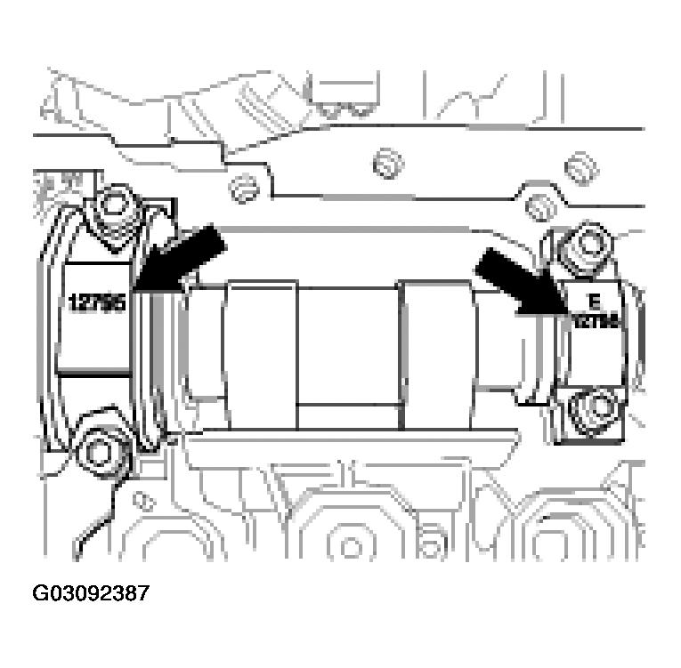
- Do not interchange the thrust bearings of the inlet and exhaust camshafts during assembly. Observe the identification -arrows-. See Fig 6.
 Courtesy of PORSCHE OF NORTH AMERICA, INC.
- Designation of inlet camshaft bearing: thrust bearing: E and pairing number on cylinder head/cylinder head cover, bearing cover of the bearing sleeve: only pairing number. See Fig 6.
- Designation of exhaust camshaft bearing: thrust bearing on chain sprocket: 1A and pairing number on cylinder head/cylinder head cover, 2nd thrust bearing: 2A and pairing number on cylinder head/cylinder head cover. See Fig 6.
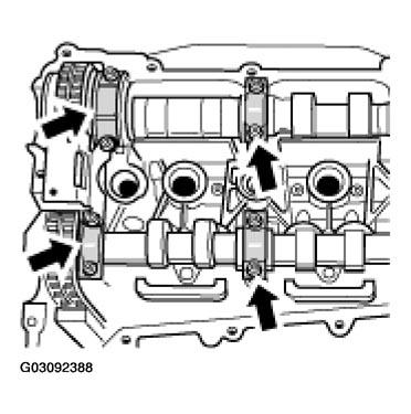
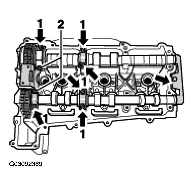
- Insert 3 thrust bearings and 1 bearing cover for the bearing sleeve of the camshafts with the guide rail for the control chain. See Fig 7. 8 bearing screws, hexagon socket: Position 6 M6 x 35 and 2 M6 x 40 for camshaft bearing and guiderail and tighten slightly. Refer to Fig 8.
 Courtesy of PORSCHE OF NORTH AMERICA, INC.
 Courtesy of PORSCHE OF NORTH AMERICA, INC.