Installing rear wiring harness
- Install repair wire in wheel housing and route in the wiring duct as far as plug connection X 2/4.
- Join wires at the connection points using a crimp connector and crimping tool. Install preassembled contacts in plug connection X 2/4.
- Colour coding of left and right hand sides of wires:
- Wire 1 - br/gn
- Wire 2 - br/bk
- Wire 3 - br
- Wire 4 - br/bu
- Wire 5 - br/wt
- br - brown
- bk - black
- bu - blue
- wt - white
- gn - green
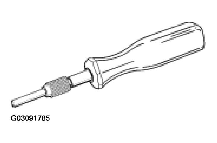
- -Unlocking tool-
to unlock the old contacts in the plug connection.
 Courtesy of PORSCHE OF NORTH AMERICA, INC.
- Unlock the old contacts of the combination wire with the unlocking tool, and remove. Install new contacts of the repair wire in the same location.
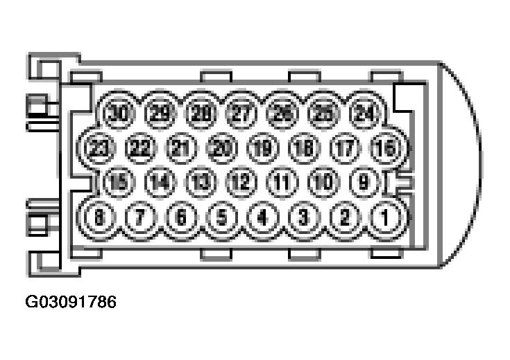
- -Plug connection X 2/4-
(white).
 Courtesy of PORSCHE OF NORTH AMERICA, INC.
- Combination wire, rear left:
- Combination wire ABS and BVA in plug connection x 2/4 (white)
- br/wt in pin 16 (ABS)
- br/wt in pin 16 (ABS)
- br/gr in pin 20 (BVA)
- Combination wire, rear right:
- br/wt in pin 18 (ABS)
- br/bu in pin 19 (ABS)
- The ground leads of the combination wires (brown) are the same on both right and left. Connection point No. 48 as shown in circuit diagram.
- Strip 10 mm of insulation off the wires.
- Push on heat-shrinking tube.
- Using a crimp connector, join brown wire of combination wire to brown wire of rear-end wiring harness
- Shrink heat-shrinking tube with a hot-air gun so that wires are watertight.
- BVA wire of combination wire (brown/green) at connection point No. 47 as shown in circuit diagram.
- Strip 10 mm of wire.
- Push on heat-shrinking tube.
- Using a crimp connector, join brown/green wire of combination wire to brown/green wire of rear-end wiring harness.
- Shrink heat-shrinking tube with a hot-air gun so that wires are watertight.
- The BVA wires of the combination wires (brown/black) are the same on both right and left. Connection point No. 46 as shown in circuit diagram.
- Strip 10 mm of wire.
- Push on heat-shrinking tube.
- Using a crimp connector, join brown/black wire of combination wire to brown/black wire of rear-end wiring harness.
- Shrink heat-shrinking tube with a hot-air gun so that wires are watertight.
- Wind commercially available PVC tape around wires.