Removal Procedure
 Courtesy of GENERAL MOTORS CORP.
- Remove the case extension housing. Refer to Case Extension Replacement .
- Remove the left drive axle from the transaxle. Refer to Wheel Drive Shaft Replacement
.
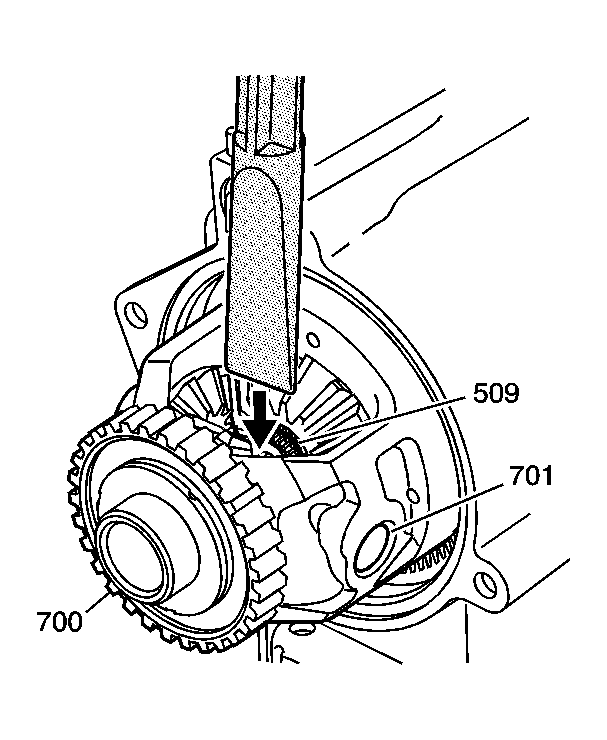
- Rotate the differential carrier until the end of the output shaft can be seen and the differential pinion shaft (701) is in a horizontal position.
- Place the J 42562
between the end of the output shaft and the differential pinion shaft. See Special Tools .
- Using a hammer, hit the end of the axle removal tool in order to compress the output shaft compression ring (512) and push the output shaft through the differential side gear.
 Courtesy of GENERAL MOTORS CORP.
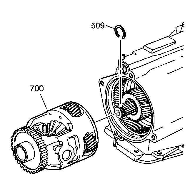
- Remove the differential carrier (700).
- Using snap ring pliers remove the compression ring (512) from the output shaft.
 Courtesy of GENERAL MOTORS CORP.
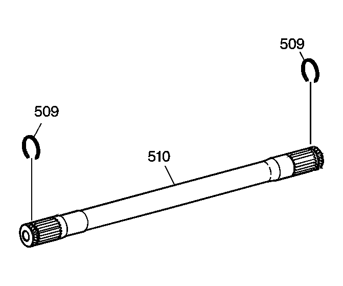
- Remove the output shaft (510) through the left wheel opening.
- Inspect the output shaft (510). Refer to Output Shaft Assemble .
 Courtesy of GENERAL MOTORS CORP.
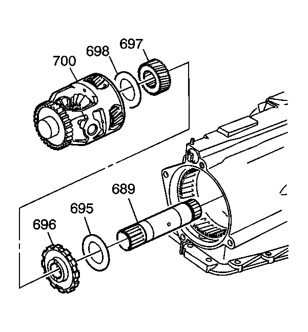
- Remove the sun gear thrust bearing (698) from the differential carrier sun gear. The bearing may be stuck to the differential carrier.
- Remove the differential carrier sun gear (697).
- Remove the park gear (696).
- Remove the internal gear thrust bearing (695) from the differential carrier internal gear.
- Remove the sun gear shaft (689.)
- Inspect the differential carrier. Refer to Differential Carrier Disassemble (FWD Only) .