52 thru 101
Transfer Case Assemble Con't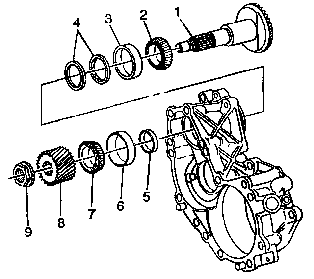
52. Disassemble the shaft (1), bearing (7), and J 44757-7 shim (5) from the case-left.
53. Install the proper size shim (5), shaft (1), bearing (7), and gear (8) to the case-left.
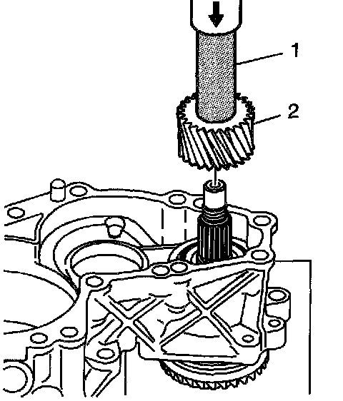
54. Lightly lubricate the splines of the driveshaft with grease.
55. Use the J 5590 (1) and a hydraulic press in order to install the bearing, proper size shim, and gear (2) onto the shaft.
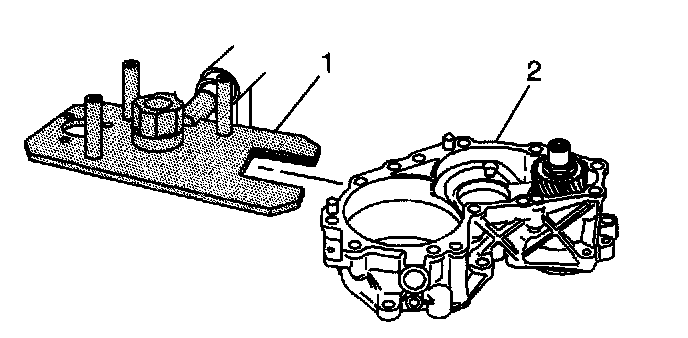
56. Install the case-left (2) onto the J 44755 (1). Align the notched area of the tool with the flat areas of the driveshaft.
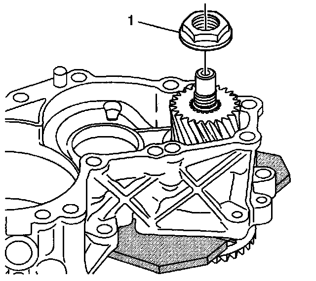
57. Install a new nut (1) onto the driveshaft.
^ Tighten the nut to 250 Nm (185 ft. lbs.).
58. Measure the rotating torque of the driveshaft. A properly assembled shaft and bearings should have a rotating torque of 1.5 Nm (13 inch lbs.).
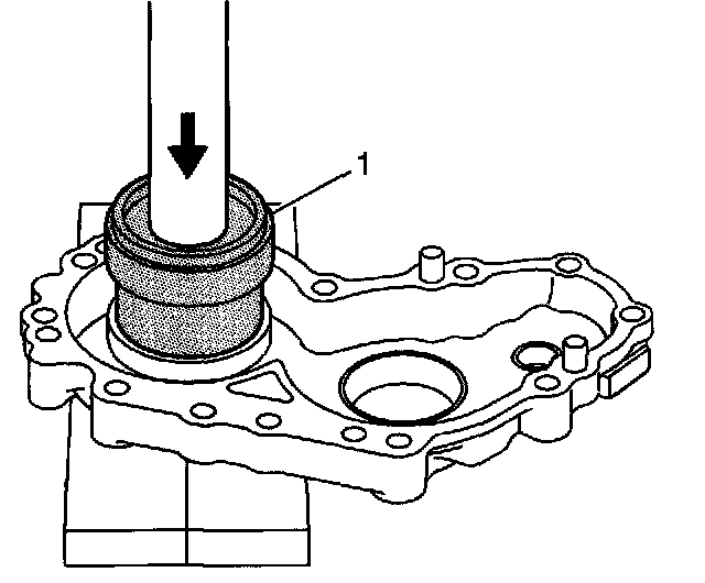
59. Use the J 44752 (1) and a hydraulic press in order to install the carrier bearing race-inner to the case-right.
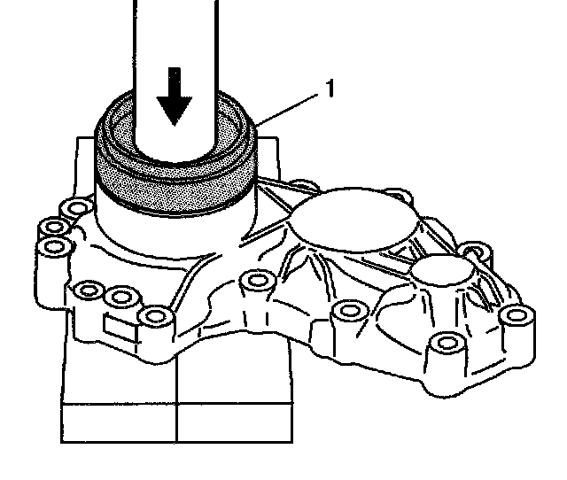
60. Use the J44752 (1) and a hydraulic press in order to install the carrier bearing race-outer to the case-right.
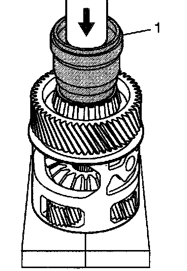
61. Use the J 44752 (1) and a hydraulic press in order to install the bearing-inner to the differential carrier.
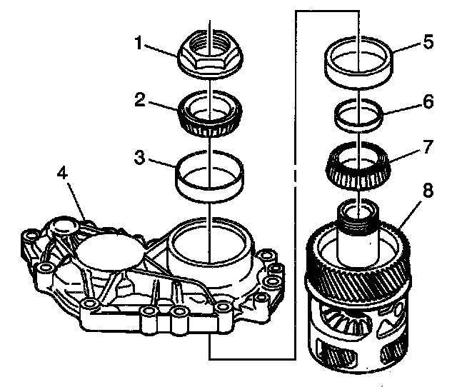
Important: The J 44757-4 shim is installed to create measurable end play and assist in determining the proper size shim for bearing preload.
62. Install the carrier (8), J 44757-4 shim (6), and bearing (2) to the case-right.
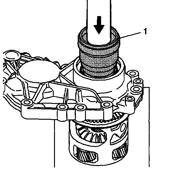
63. Use the J 44752 (1) and a hydraulic press in order to install the carrier, J 44757-4 shim, and bearing to the case-right.
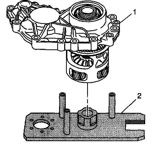
64. Install the case-right (1) onto the J 44755 (2). Position the carrier onto the post of the fixture.
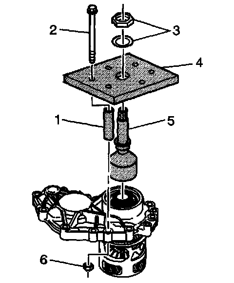
65. Install the J 44757-5 (5) onto the carrier. Tighten until snug.
66. Install the J 44757-6 (4), J 44757-8 (1), bolts (2), nuts and washers (3), and nuts (6) to the case-right.
^ Tighten the bolts to 25 Nm (18 ft. lbs.).
67. Rotate the differential carrier multiple times in both directions to ensure the bearing rollers are seated to the bearing races.
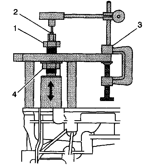
68. Install J 8001 (3) onto the J 44757-6. Position the tip (2) of the indicator onto the end of the J 44757-5.
69. Tighten the nut (4) of the J 44757-5 to preload to the bearings and position the differential carrier at the bottom of travel. Use a second wrench to hold the J 44757-5 shaft. Observe the needle on the dial. When the needle movement stops, the carrier is at bottom of travel.
70. Zero the dial indicator.
71. Loosen and back-off the nut (4).
72. Tighten the nut (1) to preload the bearings and position the carrier at the top of travel. Use a second wrench to hold the J 44757-5 shaft.
73. Record the measured value on the dial indicator. Subtract the measured value from 10 mm (0.394 inch) in order to determine the carrier shim required for proper bearing installation and preload.
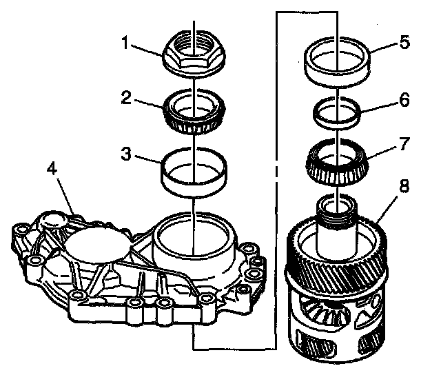
74. Disassemble the carrier (8), bearing (2), and J 44757-4 shim (6) from the case-right.
75. Install the proper size shim (6), carrier (8), and bearing (2) to the case-right.
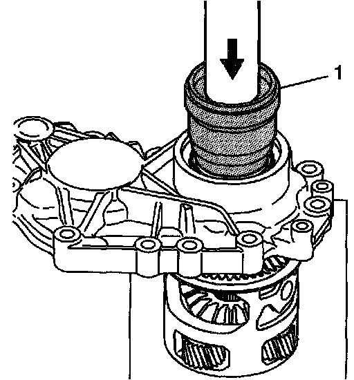
76. Use the J 44752 (1) and a hydraulic press in order to install the shaft, proper size shim, and bearing to the case-right.
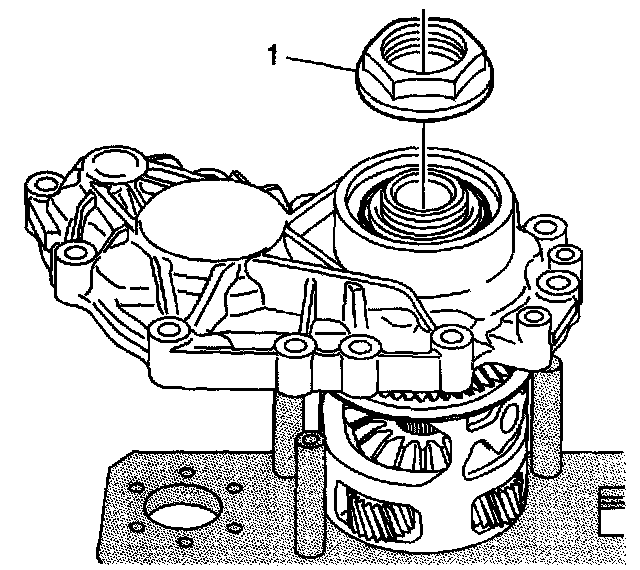
77. Install the nut (1) to the differential carrier.
^ Tighten the nut to 500 Nm (369 ft. lbs.).
78. Measure the rotating torque of the carrier. A properly assembled carrier and bearings should have a rotating torque of 1.5 Nm (13 inch lbs.).
79. Using a punch, stake the flange of the nut to the groove in the carrier shaft.
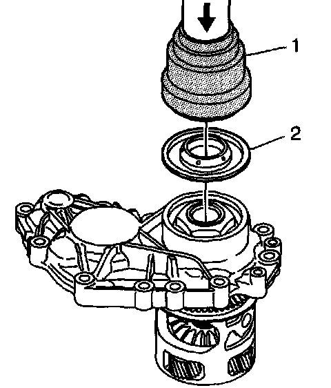
80. Use the J 44752 (1) in order to install the seal (2 to the case-right.
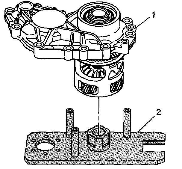
81. Remove the case-right (1) and carrier from the J 44755 (2).
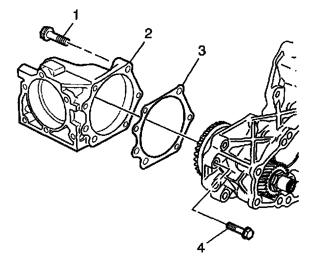
82. Install a random size shim (3), housing (2), and bolts (1 and 4) to the case-left.
^ Tighten the M8 bolts to 28 Nm (21 ft. lbs.).
^ Tighten the M 10 bolts to 54 Nm (40 ft. lbs.).
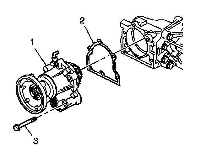
83. Apply sealant GM P/N 12346004 or equivalent to both sides of the shim (2).
84. Install the housing (1), selected shim (2), and bolts (3) to the housing.
^ Tighten the bolts to 28 Nm (21 ft. lbs.).
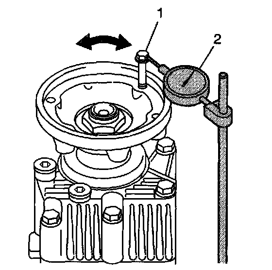
85. Install an M8 x 1.25 bolt (1) into a threaded hole in the flange.
86. Position the top of J 8001 (2) against the flat area of the bolt.
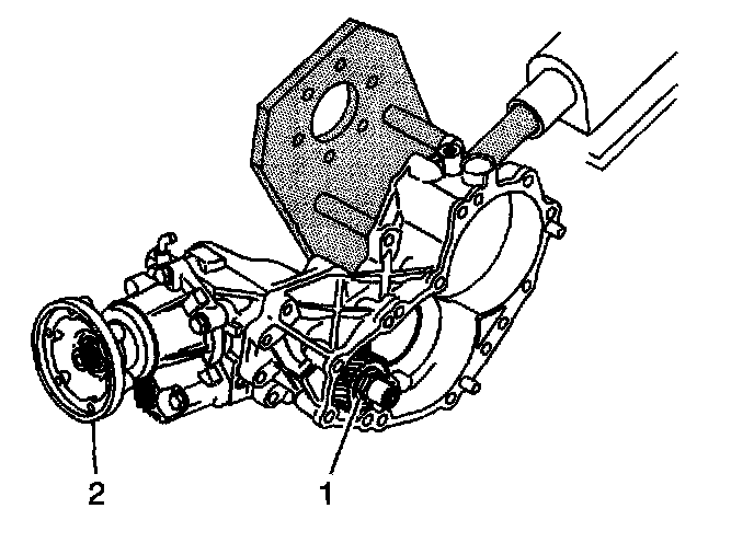
87. Install a wrench or socket onto the nut (1) of the driveshaft. Do not allow the shaft to rotate or move when measuring backlash.
88. Rotate the flange (2) left and right in order to measure the drive and driven shafts gear backlash. Measure the backlash in multiple locations. The correct gear backlash is 0.2 - 0.3 mm (0.0078 - 0.0118 inch).
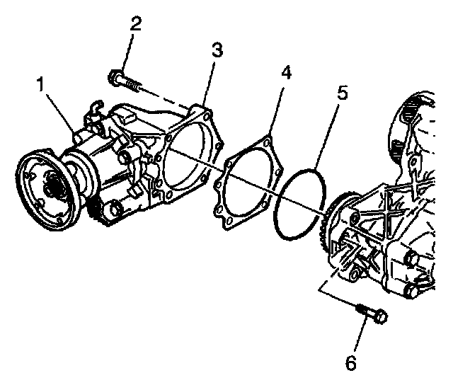
89. Select and install the correct shim (4) to obtain the proper backlash. A change in shim thickness has a one-to-one ratio and change in gear backlash.
^ A thicker shim will increase backlash.
^ A thinner shim will decrease backlash.
90. Install a new O-ring (5) during final assembly.
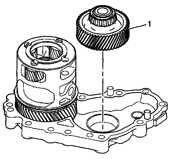
91. Apply sealant GM P/N 12346004 or equivalent to the sealing surfaces of the case-right.
92. Install the idler gear (1) to the case-right.
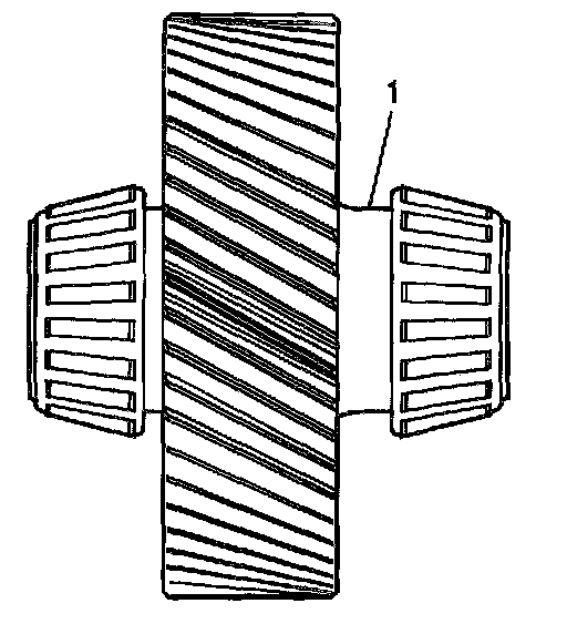
93. Install the idler gear into the case-right. The side of the gear with the long flange area (1) should be installed to the case-right.
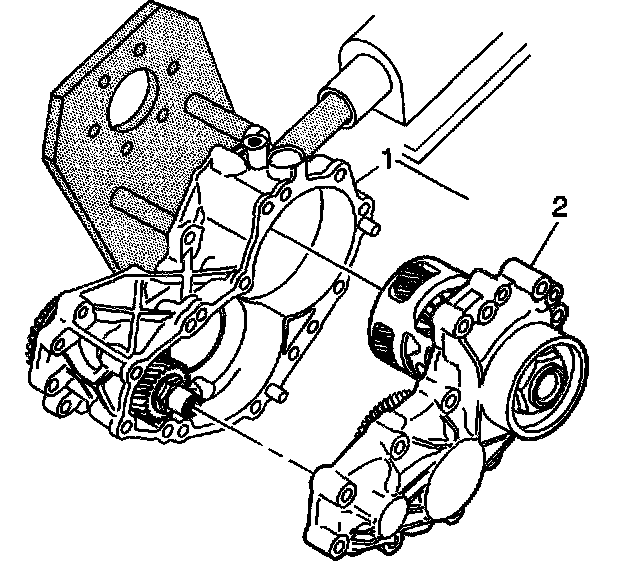
94. Rotate the J 44755 90 degrees.
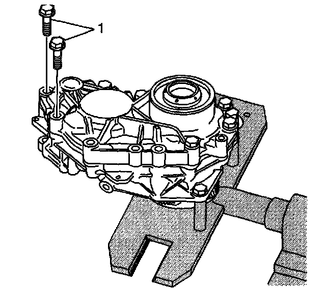
95. Install the case-right (2) to the case-left (1).
96. Install the bolts (1) to the case.
^ Tighten the bolts to 54 Nm (40 ft. lbs.).
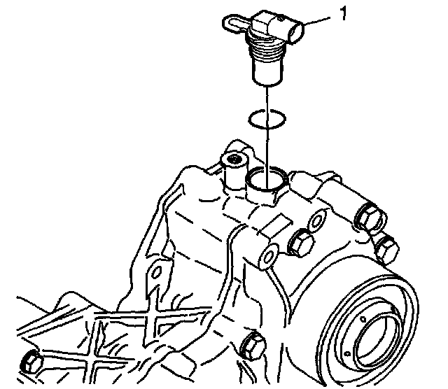
97. Install the speed sensor (1) and O-ring.
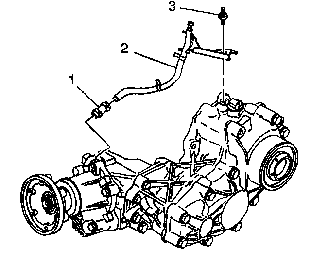
98. Install the hose and clamp (1), vent hose (2), and bolt (3).
^ Tighten the vent hose/speed sensor bolt to 10 Nm (106 inch lbs.).
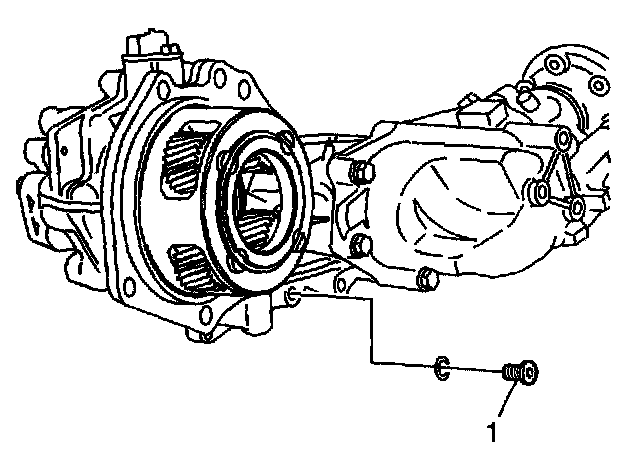
99. Install the transmission oil drain plug (1) and gasket.
^ Tighten the drain plug to 32 Nm (24 ft. lbs.).
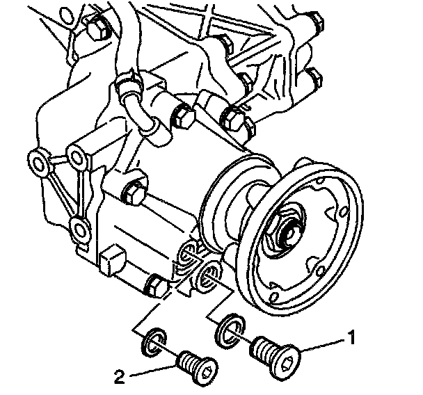
100. Install the gear oil drain plug (1) and gasket.
^ Tighten the drain plug to 32 Nm (24 ft. lbs.).
Important: The end play clearance between the transmission and transfer case internal components is adjusted by selection of the proper size selective washer (located behind the transmission sun gear). The transmission-to-transfer case washer selection procedure must be performed each time a transmission and/or transfer case assembly or the internal components (excluding gaskets and seals) are replaced.
101. Perform the transfer case selective washer measurement procedure as required.