1 thru 51
Transfer Case Assemble^ Tools Required
- J 5590 Crankshaft Sprocket Installer
- J 8001 Dial Indicator Set
- J 36797 Seal Installer
- J 44752 Bearing, Race, and Seal Installer
- J 44753 Bearing and Seal Installer
- J 44755 Holding Fixture
- J 44757 Shim Selection Kit
- J 44907 Bearing Installer
- J 44908 Bearing Race Installer
Important:
^ The transfer case is assembled for proper gear tooth clearances, backlash, and bearing preloads with selective shims.
^ Do not assemble the internal components dry. Lightly lubricate the bearing races, bearings, gears, and oil seals with the proper lubricant. Components in the transaxle portion of the transfer case should be lubricated with Dextron III GM P/N 12378470 or equivalent. Components in the hypoid gear portion of the transfer case should be lubricated with GM P/N 12378514.
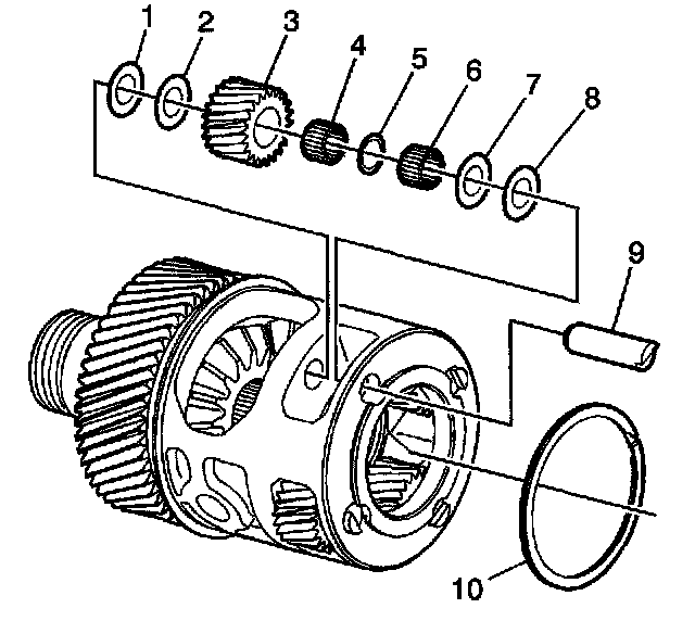
1. Install the needle bearings (4 and 6) and washer (5) to the gear (3), if required.
2. Install the pin (9), gear (3), and washers (1, 2, 7, and 8) to the differential carrier, if required.
3. Install the ring (10) to the carrier, if required.
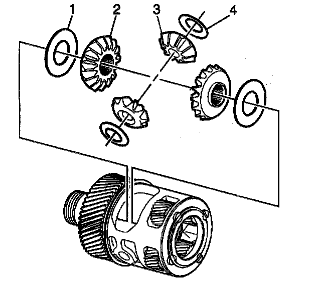
4. Install the side gears (2), pinion gears (3), and washers (1 and 4) to the carrier, if required.
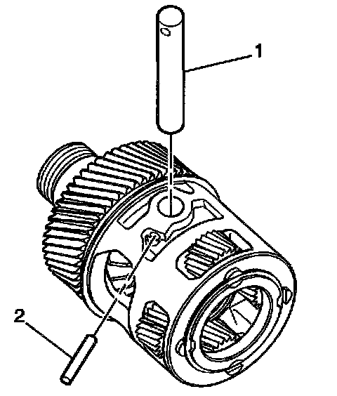
5. Install the shaft (1) and roll pin (2) to the carrier, if required.
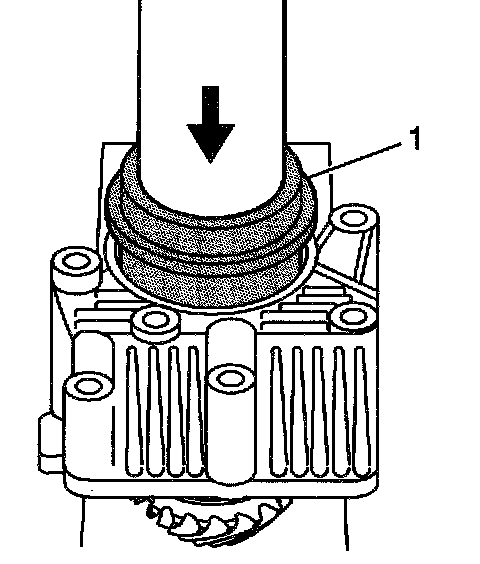
6. Use the J 44908 (1) and a hydraulic press in order to install the outer bearing race to the extension housing.
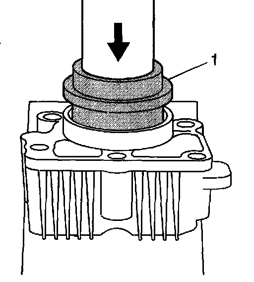
7. Use the J 44908 (1) and a hydraulic press in order to install the inner bearing race to the extension housing.
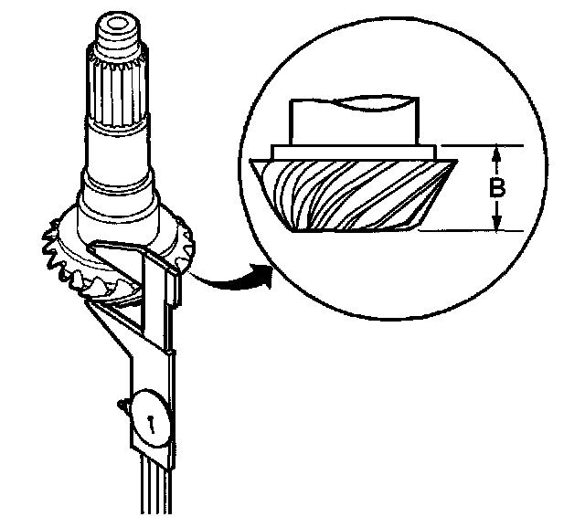
8. Measure the distance between the flange on the driven shaft and the end of the pinion. Record the value as dimension B.
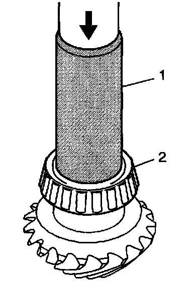
9. Use the J 44907 (1) and a hydraulic press in order to install the inner bearing (2) to the drivenshaft.
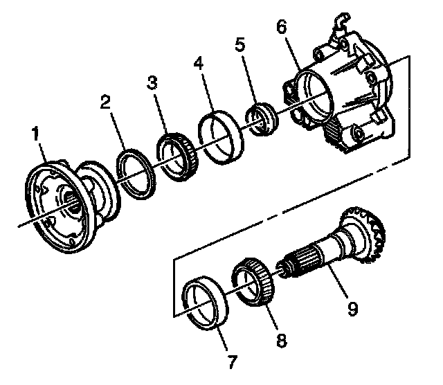
10. Install the drivenshaft (9), NEW spacer (5), and bearing (3) into the extension housing (6).
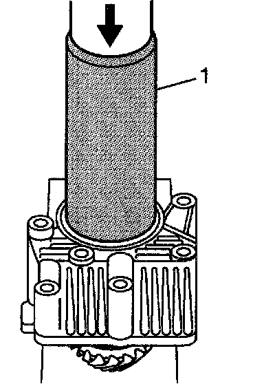
11. Use the J 5590 (1) and a hydraulic press in order to install the bearing onto the shaft.
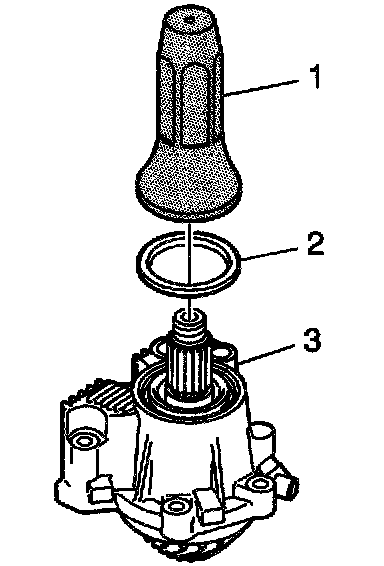
12. Use the J 36797 (1) in order to install a new oil seal (2) into the extension housing (3).
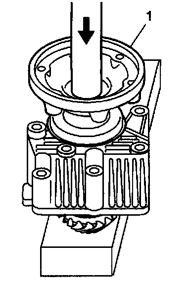
13. Lightly lubricate the splines of the drivenshaft with grease.
14. Install the flange (1) onto the shaft using a hydraulic press.
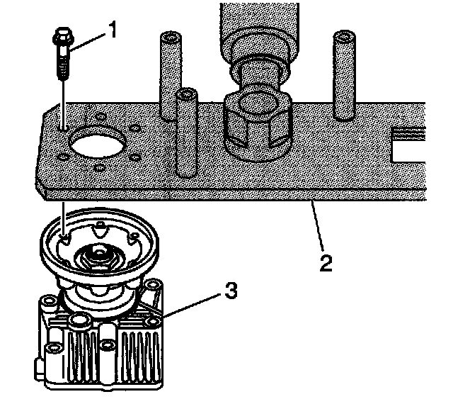
Notice: Refer to Fastener Notice in Service Precautions.
15. Install the extension housing assembly (3) and bolts (1) to the J 44755 (2).
^ Tighten the bolts to 25 Nm (18 ft. lbs.).
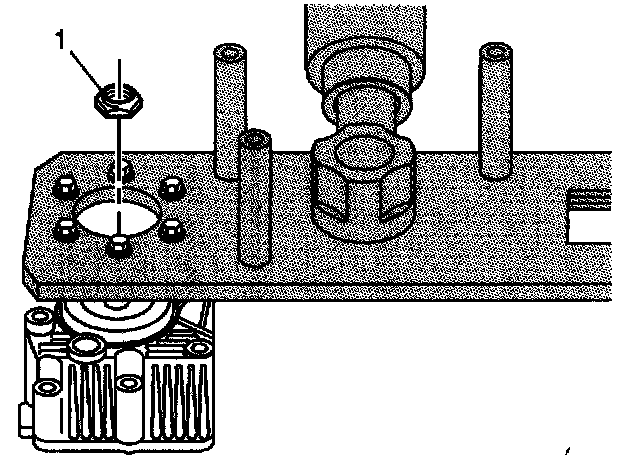
16. Install a new nut (1) onto the shaft.
^ Tighten the nut, with new bearings to 250 Nm (185 ft. lbs.).
^ Tighten the nut, with used bearings to 200 Nm (148 ft. lbs.).
17. Remove the extension housing assembly and bolts from the J 44755.
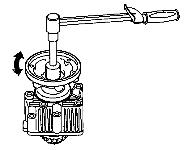
18. Measure in both directions, the rotating torque of the drivenshaft. A properly assembled shaft and NEW bearings should have a rotating torque of 1.5 Nm (13 inch lbs.). When reusing drivenshaft bearings, the rotating torque should equal the value recorded during disassembly. Tighten the flange nut as required to achieve the proper rotating torque value.
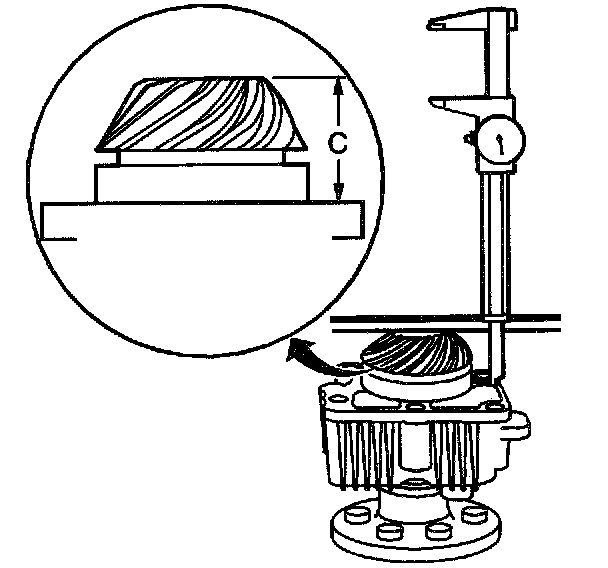
19. Measure the distance between the end of the pinion and the extension housing seal surface. Record the value as dimension C.
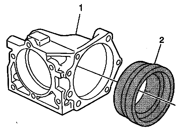
20. Install the J 44757-3 (2) into the bore of the housing (1).
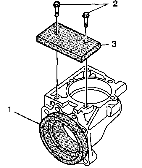
21. Install J 44757-9 (3) and bolts (2) to the housing (1).
^ Tighten the bolts to 25 Nm (18 ft. lbs.).
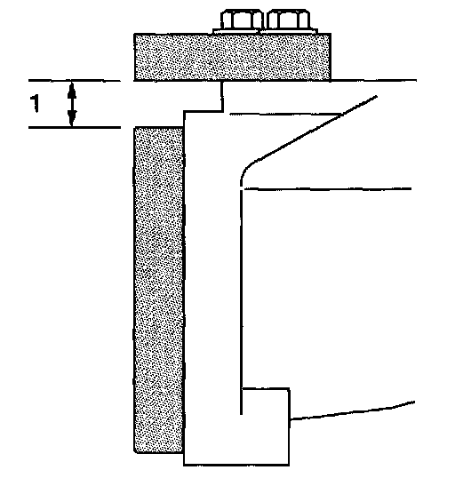
22. Measure the distance (1) between the J 44757-3 and the J 44757-9 using a feeler gauge. Add the measured value (1) to 67.3 mm (2.65 inch). Record the value as dimension D.
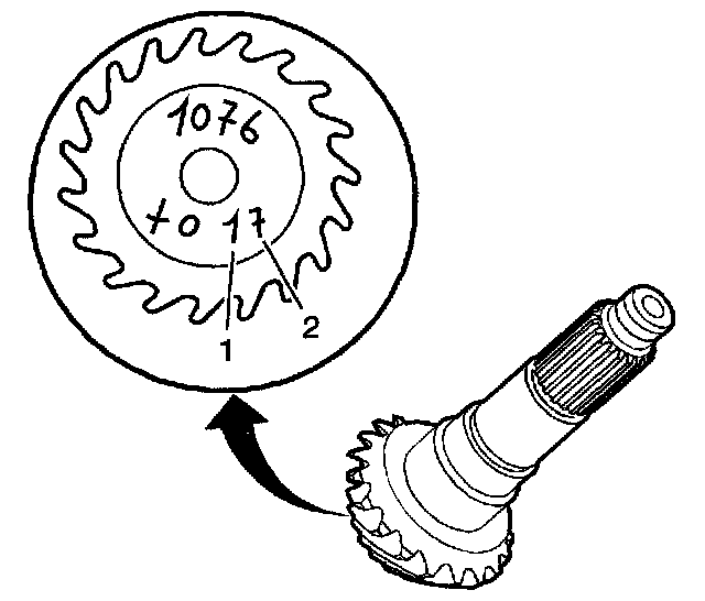
23. Determine if the drivenshaft has a plus, minus, or zero value etched onto the end of the gear.
Note that the handwritten 1 (1) and 7 (2) are similar. The 7 (2) will have a line drawn through the number.
24. Calculate the extension housing shim thickness.
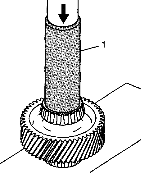
25. Use the J 5590 (1) and a hydraulic press in order to install the bearings onto the idler gear.
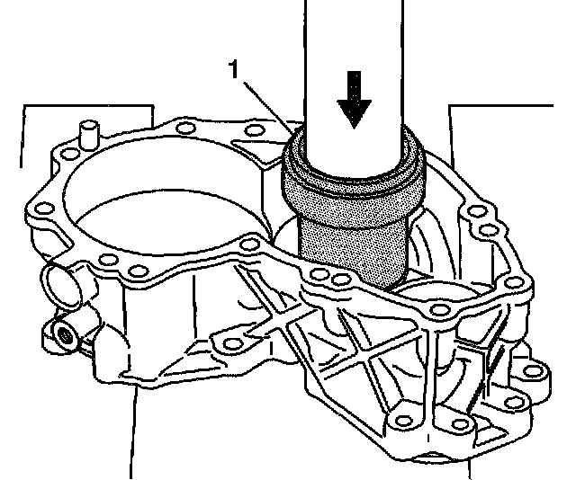
26. Use the J 44752 (1) and a hydraulic press in order to install the bearing race into the cover-left.
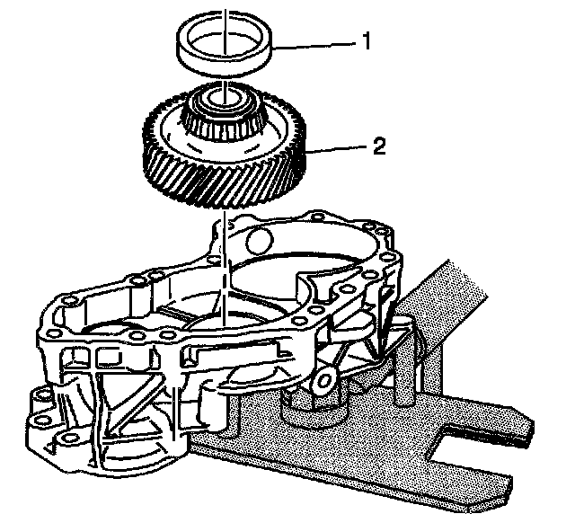
27. Install the idler gear (2) and bearing race (1) to the case-left.
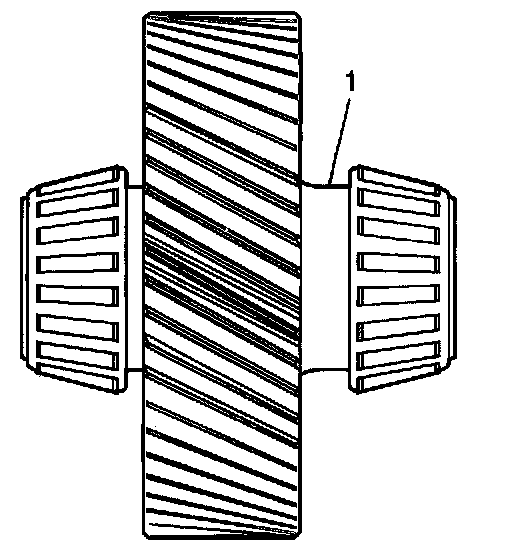
28. Inspect the gear for proper installation. The side of the gear with the long flange area (1) should be installed to the case-right side.
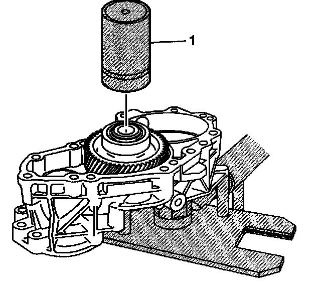
29. Install the J 44757-1 (1) to the idler gear and race.
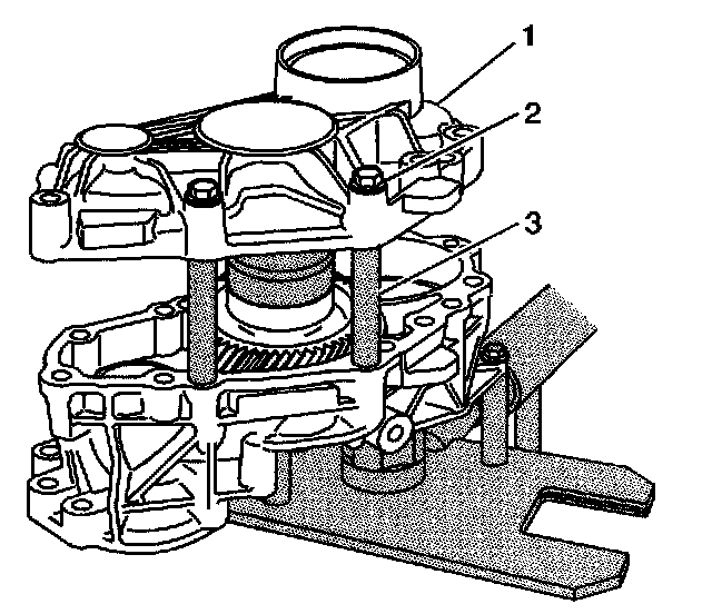
30. Install the cover-right (1), bolts (2), and J 44757-8 (3) to the case-left.
^ Tighten the bolts to 25 Nm (18 ft. lbs.).
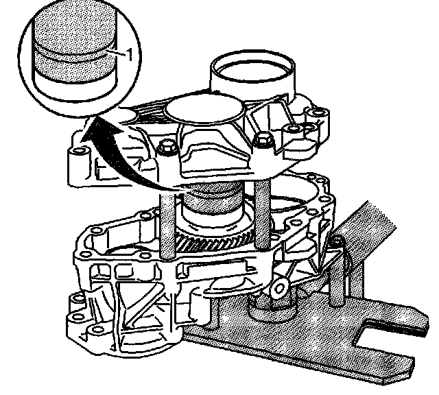
31. Using a feeler gauge, measure the gap (1) in the J 44757-1. The measured amount is the idler gear bearing shim thickness.
32. Disassemble the case-right and tools from the case-left.
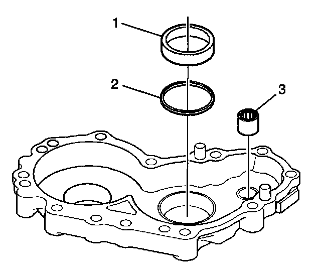
33. Install the selected idler gear bearing shim (2) and bearing race (1) to the case-right.
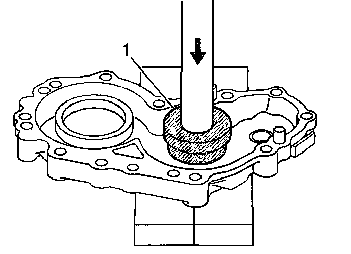
34. Use the J 44752 (1) and a hydraulic press in order to install the bearing race to the case-right.
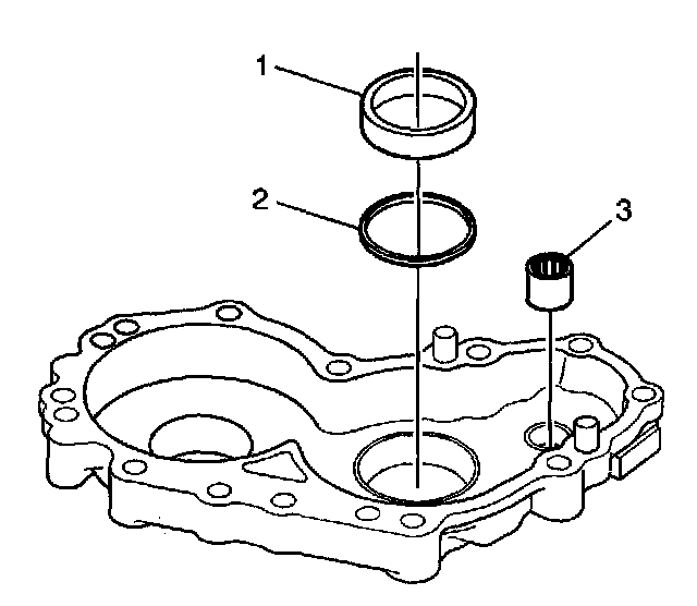
35. Install the driveshaft bearing (3) to the case-right.
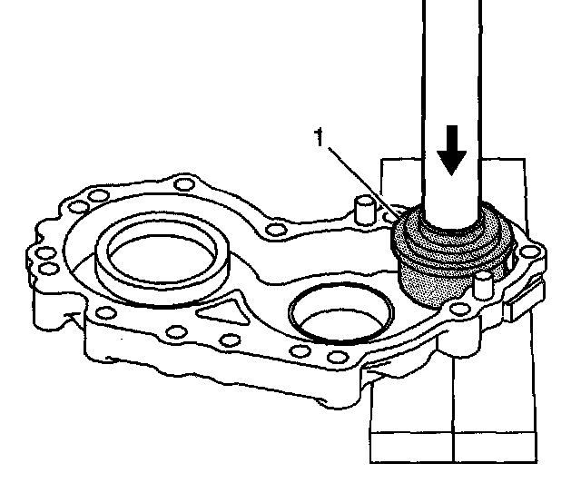
36. Use the J 44753 (1) and a hydraulic press in order to install the bearing to the case-right.
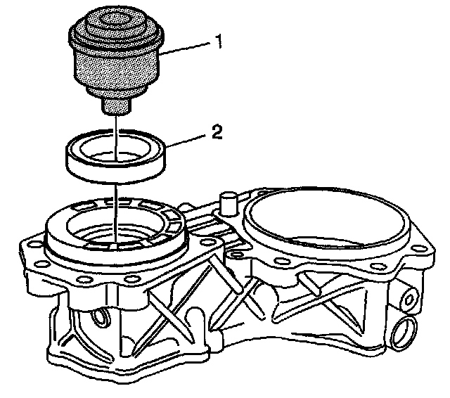
37. Use the J 44753 (1) to install the oil seal-transaxle side (2) to the case-left. Install until the seal bottoms in the case-left bore.
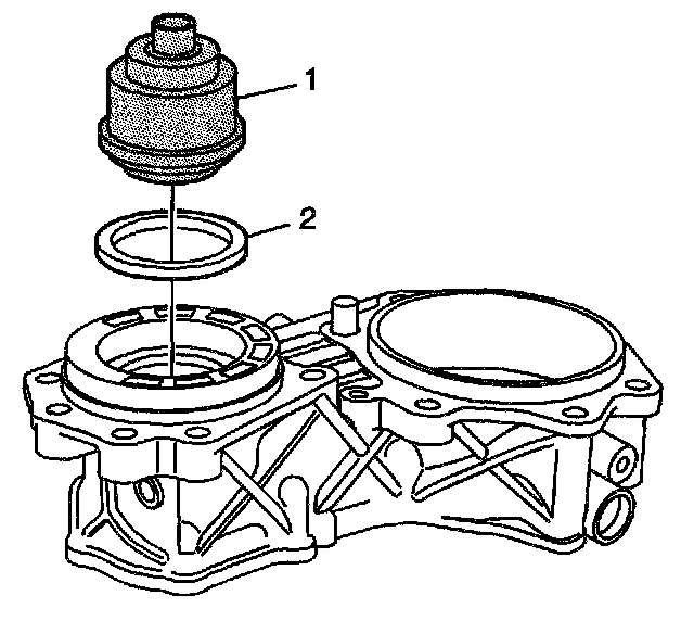
38. Use the J 44753 (1) to install the oil seal-gear oil side (2) to the case-left. Install until the tool bottoms against the case-left.
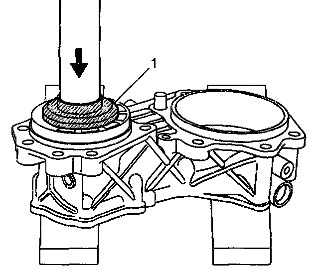
39. Use the J 44908 (1) and a hydraulic press in order to install the bearing races to the case-left.
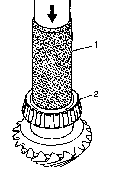
40. Use the J 44907 (1) and a hydraulic press in order to install the inner bearing (2) to the driveshaft.
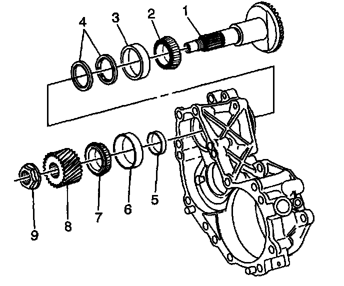
Important: The J 44757-7 shim is installed to create measurable end play and to assist in determining the proper size shim for bearing preload.
41. Assemble the shaft (1), J 44757-7 shim (5), and bearing (7) to the case-left.
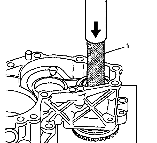
42. Use the J 5590 (1) and a hydraulic press in order to install the shaft, J 44757-7 shim, and bearing to the case-left.
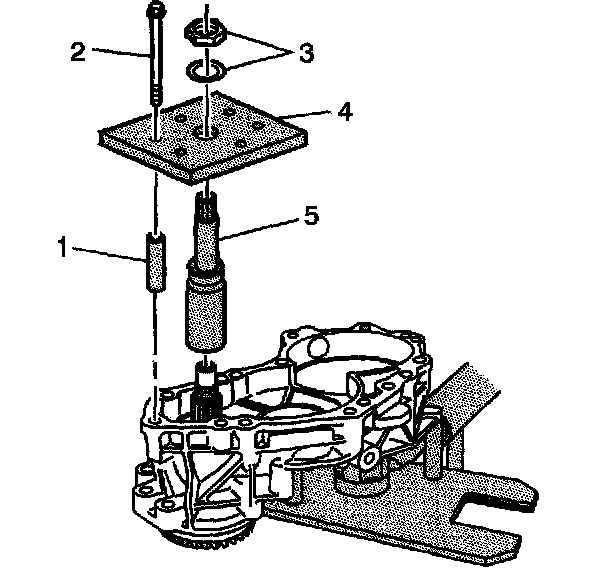
43. Install the J 44757-2 (5) onto the driveshaft. Tighten until snug.
44. Install the J 44757-6 (4), J 44757-8 (1), bolts (2), and nuts and washers (3) to the case-left.
^ Tighten the bolts to 25 Nm (18 ft. lbs.).
45. Rotate the driveshaft, multiple times in both directions to ensure the bearing rollers are seated to the bearing races.
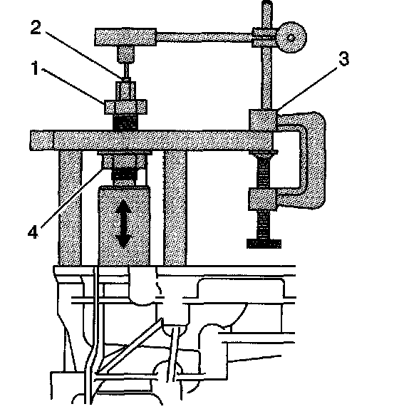
46. Install J 8001 (3) onto the J 44757-6. Position the tip (2) of the indicator onto the end of the J 44757-2.
47. Tighten the nut (4) of the J 44757-2 to preload to the bearings and position the shaft at the bottom of travel. Use a second wrench to hold the J 44757-2 shaft. Observe the needle on the dial. When the needle movement stops, the shaft is at bottom of travel.
48. Zero the dial indicator.
49. Loosen and back-off the nut (4).
50. Tighten the nut (1) to preload the bearings and position the shaft at the top of travel. Use a second wrench to hold the J 44757-2 shaft.
51. Record the measured value on the dial indicator. Subtract the measured value from 6.0 mm (0.236 inch) in order to determine the driveshaft shim required for proper bearing installation and preload.