Front
Wheel Drive Shaft Outer Joint and Seal Replacement - Front^ Tools Required
- J 42572 Drive Shaft Seal Clamp Pliers
Disassembly Procedure
1. Wrap a shop towel around the axle shaft.
2. Place the wheel drive shaft horizontally in a bench vise.
3. Remove the large seal retaining clamp from the CV joint seal.
Use a side cutter or other suitable tool and discard the clamp.
4. Remove the small seal retaining clamp from the joint seal.
Use a side cutter or other suitable tool and discard the clamp.
5. Separate the seal from the joint outer race at the large diameter end.
6. Position the seal behind the joint face.
7. Wipe the grease from the face of the joint inner race, cage, balls, etc.
8. Remove the outer joint from the axle shaft.
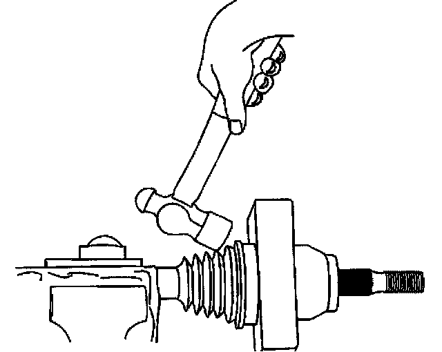
8.1. Hold the joint housing.
8.2. Position a wood block between the seal and the joint (along the joint face).
8.3. Strike the wood block with a hammer to compress the axle shaft retaining clip.
8.4. Continue to strike the wood block in order to remove the outer joint from the axle shaft.
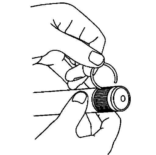
9. Remove the axle shaft retaining ring from the axle shaft.
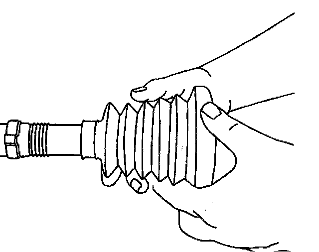
10. Remove the seal from the axle shaft.
11. Remove the wheel drive shaft from the vise.
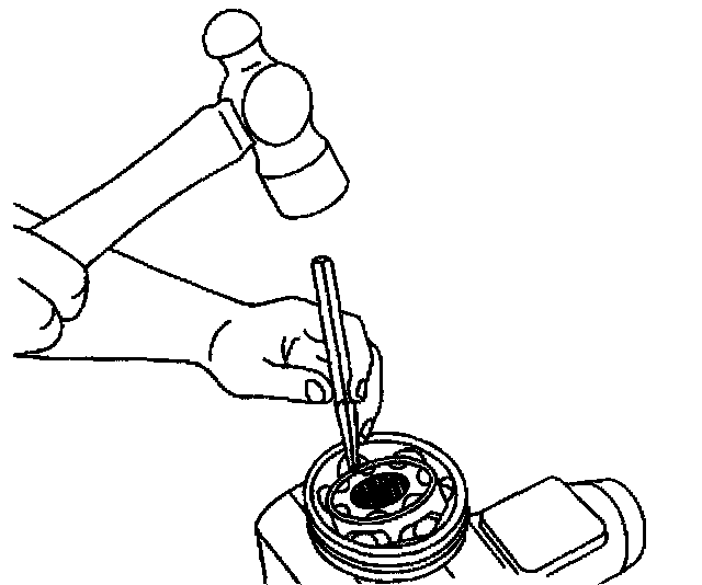
12. Wrap a shop towel around the joint outer race splined shaft.
13. Place the outer race vertically in a bench vise.
14. Make a ball accessible for removal.
Tap gently on the joint cage, using a brass drift and a hammer, in order to drive a ball toward the bottom of its track. The opposing ball will be made accessible for removal.
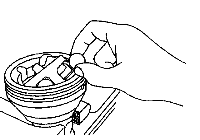
15. Remove the exposed ball.
Use a small screwdriver to aid in removal if necessary.
16. Position the cage and inner race so they are level.
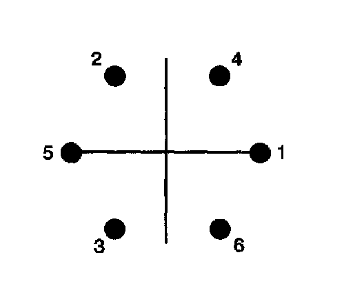
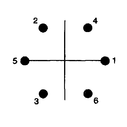
17. Repeat steps 14 through 16 in the removal sequence as shown until you remove all 6 balls.
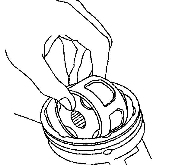
18. Position the cage and the inner race 90 degrees to the centerline of the outer race.
19. Align the cage windows with the lands of the outer race.
20. Lift to remove the cage and the inner race from the outer race.
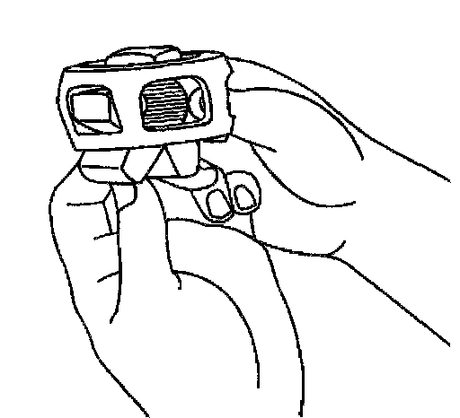
21. Position the cage and inner race so that the larger radius corners of the cage windows are up.
22. Rotate the inner race 90 degrees to the centerline of the cage.
23. Align the lands of the inner race with the windows of the cage.
24. Insert an inner race land into a cage window.
25. Pivot the inner race down and remove it from the cage.
Important: All traces of old grease and any contaminates must be removed.
26. Clean the following thoroughly with clean solvent:
^ The inner race
^ The outer race
^ The cage
^ The balls
^ The axle shaft exposed end.
27. Thoroughly air dry all the parts.
Assembly Procedure
Notice: Wheel drive shaft boots, seals and clamps should be protected from sharp objects any time service is performed on or near the wheel drive shaft(s). Damage to the boot(s), the seal(s) or the clamp(s) may cause lubricant to leak from the joint and lead to increased noise and possible failure of the wheel drive shaft.
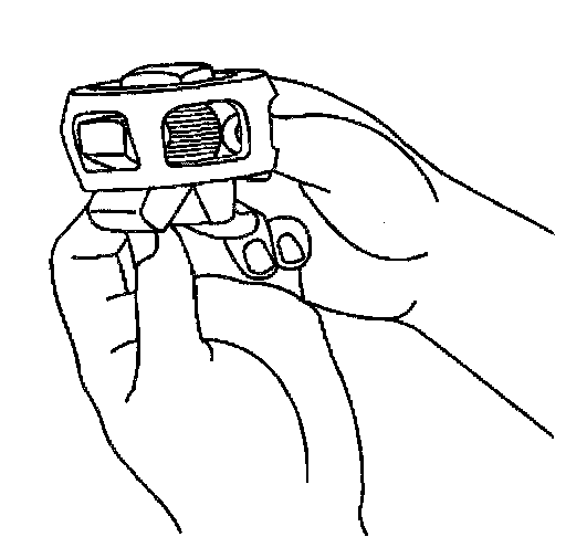
1. Position the cage so the larger radius corners of the cage windows are up.
2. Position the inner race 90 degrees to the centerline of the cage.
3. Begin to insert the inner race up through the bottom of the cage.
4. Align a land of the inner race to a window of the cage.
5. Insert the inner race land into the cage window.
6. Rotate the remainder of the inner race into the cage.
7. Rotate the inner race within the cage so that the grooved surface of the inner race is facing up.
8. Align the inner race ball tracks with the cage windows.
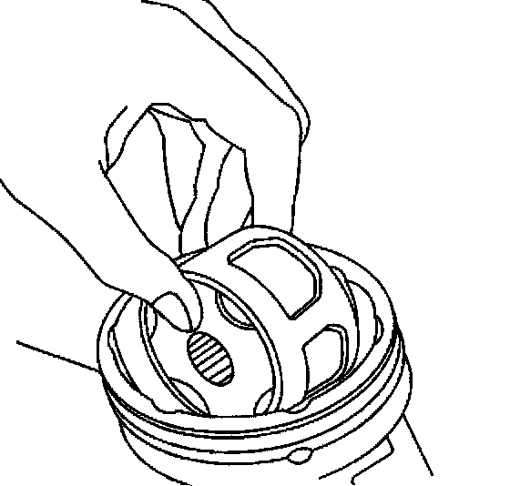
9. Wrap a shop towel around the joint outer race splined shaft.
10. Place the outer race vertically in a bench vise.
11. Position the cage and inner race 90 degrees to the centerline of the outer race.
12. Align 2 cage windows at 0 and 180 degrees.
Rotate the inner race and cage assembly in the vertical plane.
13. Align the two windows at 0 and 180 degrees with 2 of the outer race lands.
14. Insert the cage and inner race into the outer race.
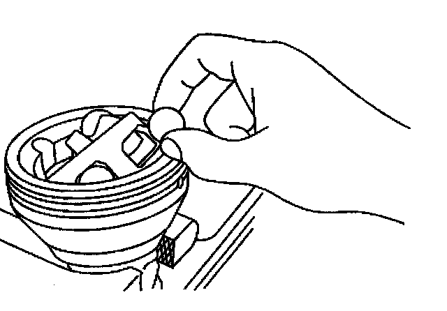
Important: The larger radius corners of the cage windows should be positioned up and the grooved surface of the inner race should be visible.
15. Position the cage and inner race so they are level.
16. Align the cage windows and inner race ball tracks with the outer race ball tracks.
Rotate the appropriate component(s).
17. Position a cage window and inner race ball track for ball installation.
17.1. Press down on the cage following one of the outer race ball tracks. The opposing cage window and inner race ball track will be accessible for ball installation.
17.2. After installing the first ball, use a brass drift and a hammer to tap gently on the cage, in order to drive the cage and inner race down completely.
Important: No gap should exist between the ball and the inner race ball track.
18. Insert a ball through the cage window onto the inner race ball track.
Tap the ball lightly with a plastic tipped hammer.
19. Position the cage and inner race so they are level.
Important: The ball installation sequence must be followed as shown.
20. Repeat steps 17 through 19 in the installation sequence as shown until all 6 balls are installed.
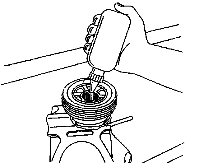
21. Insert approximately 60 percent of the grease from the service kit into the outer joint.
21.1. Spread the grease onto the ball tracks, the balls, the cage and the inner race.
21.2. Spread the remainder of the grease into the bottom of the outer race.
22. Remove the outer joint from the bench vise.
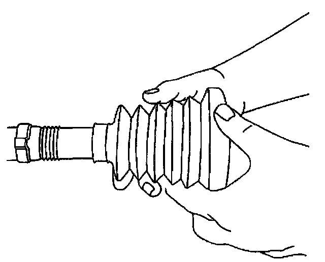
23. Wrap a shop towel around the axle shaft.
24. Place the wheel drive shaft horizontally in a bench vise.
25. Install a new small seal retaining clamp onto the axle shaft.
26. Install the seal onto the axle shaft.
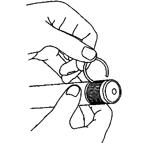
27. Install a new retaining ring to the axle shaft.
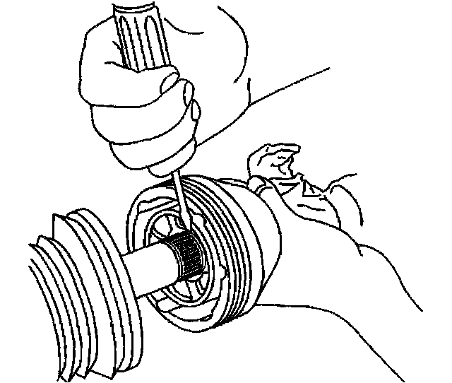
28. Position the outer joint horizontally.
29. Engage the inner race splines onto the axle shaft splines.
30. Compress the axle shaft retaining ring.
30.1. Press 1 end of the retaining ring, using a flat bladed tool, into the axle shaft groove while firmly pressing the outer joint onto the axle shaft.
30.2. Continue to work around the retaining ring until it is compressed.
Important: The axle shaft and inner race must be fully seated to each other.
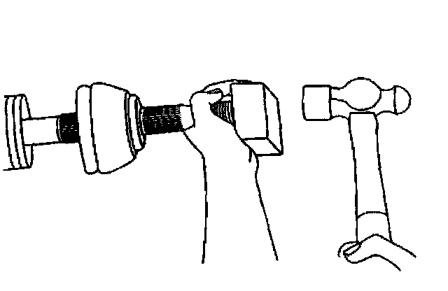
31. Install the outer joint to the axle shaft.
31.1. Position a wood block squarely over the end of the outer joint threaded shaft.
31.2. Use a hammer to drive the outer joint onto the shaft.
31.3. Continue to drive the outer joint until the outer joint seats fully onto the axle shaft.
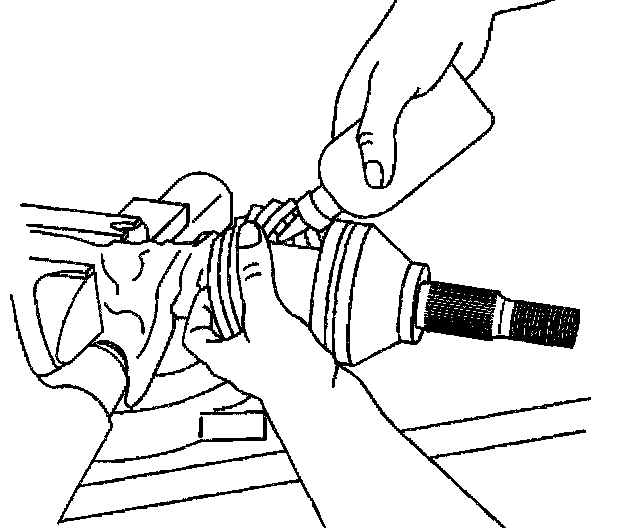
32. Insert the remaining grease from the service kit into the seal.
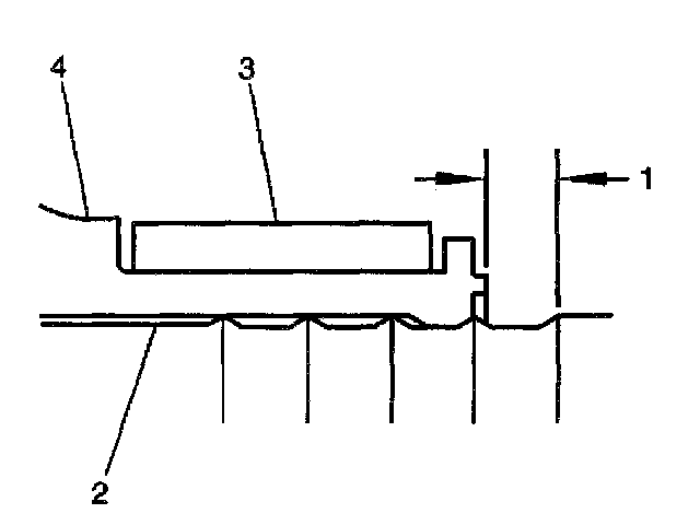
33. Position the small seal retaining clamp (3) onto the neck of the seal (4).
34. Position the seal and small retaining clamp to the axle shaft (2) as shown.
35. Measure the distance (1) between the edge of the seal and the edge of the last axle shaft groove closing edge; adjust fit accordingly.
^ 2.5 mm (0.10 inch)
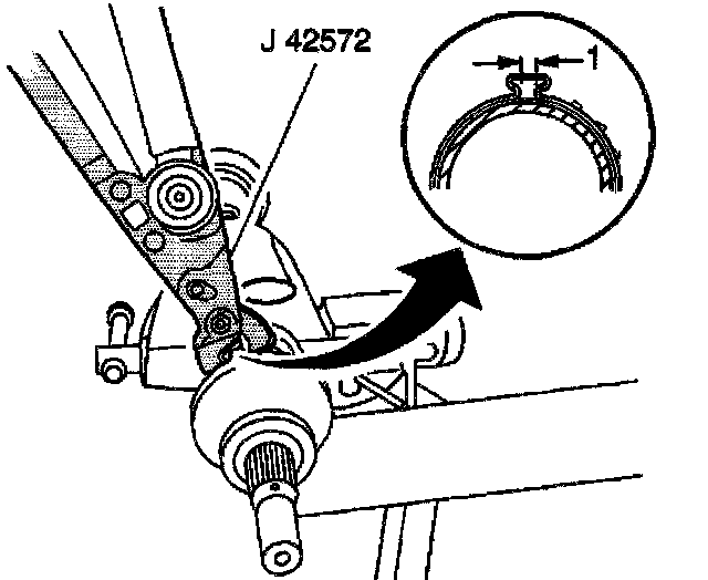
Notice: Refer to Fastener Notice in Service Precautions.
Important: The seal retaining clamp must not be over-tightened or under-tightened.
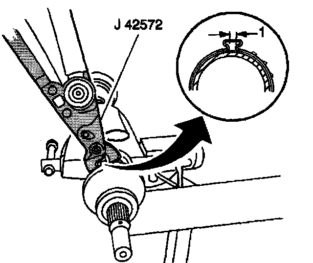
36. Using the J 42572, crimp the small seal retaining clamp.
^ Tighten the small seal retaining clamp to 136 Nm (100 ft. lbs.).
37. Measure the gap width (1) in order to ensure it is between 2 and 3 mm (0.079 and 0.118 inch).
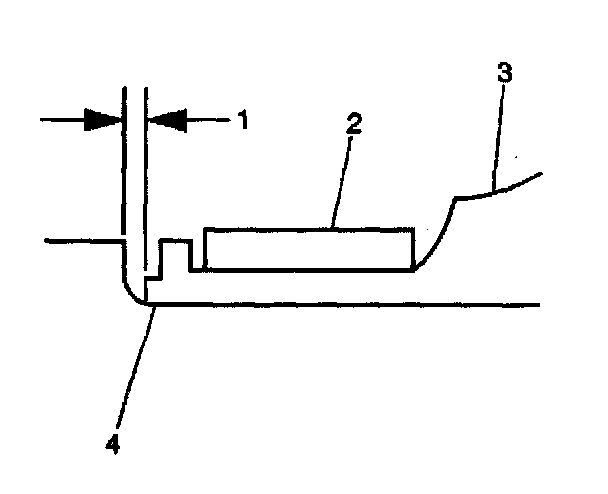
38. Position the large seal retaining clamp (2) onto the seal (3).
39. Position the seal and large retaining clamp to the joint outer race (4) as shown.
40. Measure the distance (1) between the edge of the seal and the edge of the joint outer race last groove closing edge; adjust fit accordingly.
^ 0.8 mm (0.03 inch)
Important: The seal must not be dimpled, stretched or out of shape in any way.
41. Inspect the seal for proper shape.
If the seal is NOT shaped correctly, equalize the pressure in the seal by lifting the seal edge slightly and shape the seal properly by hand.
42. Inspect the seal for damage.
If the seal has been cut or punctured during assembly, you must discard and replace the seal.
Important: The seal retaining clamp must not be over-tightened or under-tightened.
43. Using the J 42572, crimp the large seal retaining clamp.
^ Tighten the large seal retaining clamp to 136 Nm (100 ft. lbs.).
44. Measure the gap width (1) in order to ensure it is between 2 and 3 mm (0.079 and 0.118 inch).
45. Inspect the outer CV joint and wheel drive shaft for smooth operation. This will also distribute the grease within the joint.
45.1. Hold the wheel drive shaft vertically, with the outer joint at the bottom.
45.2. Rotate the wheel drive shaft four or five times in a circular motion.