Front
Wheel Drive Shaft Inner Joint and Seal Replacement - Front^ Tools Required
- J 42572 Drive Shaft Seal Clamp Pliers
Disassembly Procedure
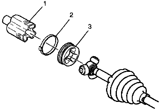
1. Remove the small seal clamp from the wheel drive shaft bar using side cutters and discard the clamp.
Important: Do not cut through the wheel drive shaft inboard seal and damage sealing surface of the outer housing and the trilobal tri-pot bushing.
2. Remove the large seal clamp (2) from the tri-pot joint with side cutters and discard the clamp.
3. Separate the wheel drive shaft inboard seal from the trilobal tri-pot bushing (3).
4. Slide the seal away from the joint along the wheel drive shaft bar.
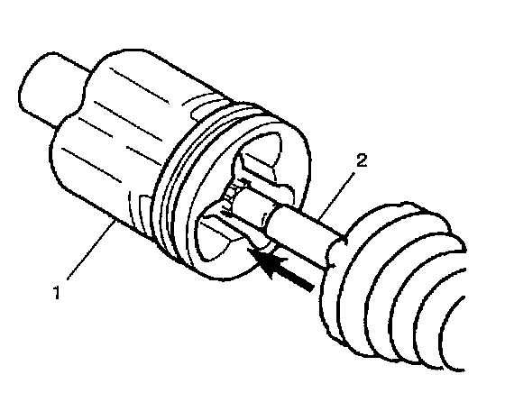
5. Remove the housing (1) from the tri-pot joint spider and the wheel drive shaft bar (2).
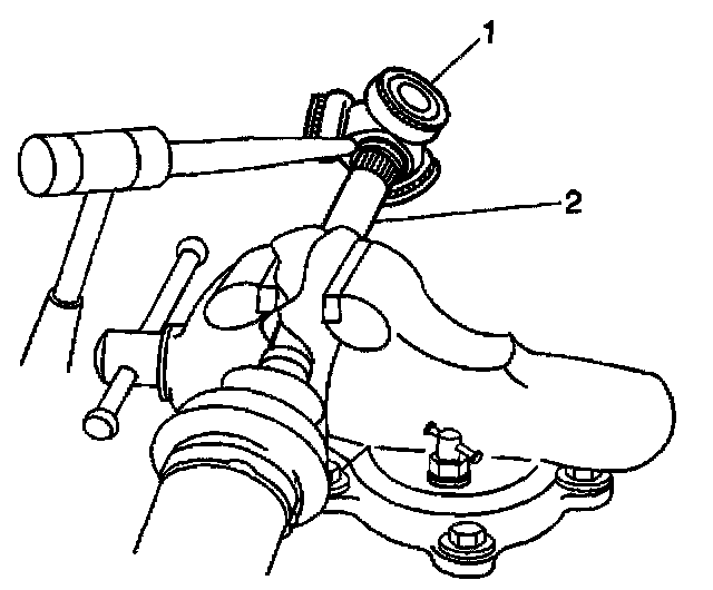
6. Using a brass drift and hammer, carefully tap around the tri-pot spider face in order to compress the barrel retaining ring on the wheel drive shaft bar.
7. Remove the tri-pot spider (1) from the wheel drive shaft bar (2).
8. Remove and discard the barrel retaining ring from the wheel drive shaft bar.
9. Remove the joint seal from the wheel drive shaft bar.
10. Inspect the following parts for damage or wear:
^ The wheel drive shaft inboard seal
^ The tri-pot joint spider assembly
^ The housing
^ The trilobal tri-pot bushing
Assembly Procedure
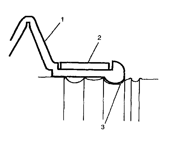
1. Place the new small seal clamp (2) onto the small end of the joint seal (1). Slide the joint seal (1) and the small seal clamp (2) onto the wheel drive shaft bar.
2. Position the small end of the joint seal (1) into the joint seal groove (3) on the wheel drive shaft bar.
Notice: Refer to Fastener Notice in Service Precautions.
3. Using the J 42572, crimp the small seal retaining clamp.
^ Tighten the clamp to 136 Nm (100 ft. lbs.).
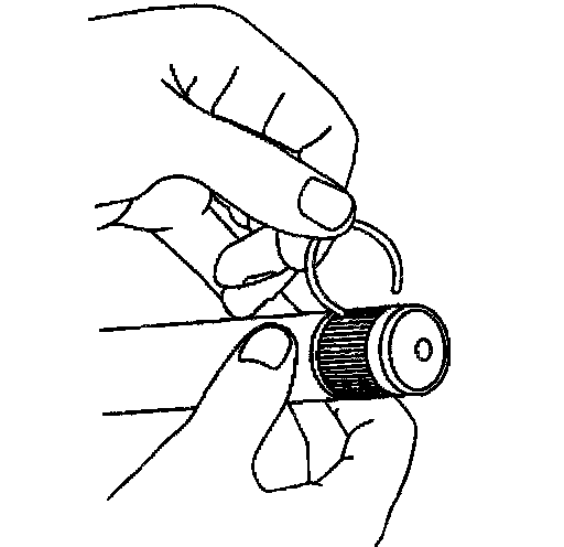
4. Install a new barrel retaining ring to the wheel drive shaft bar.
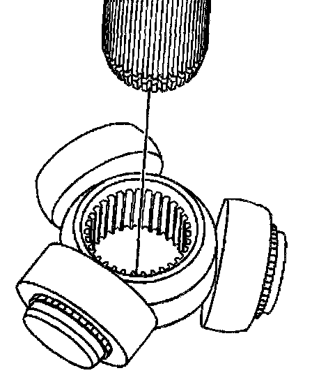
Important: Ensure that the beveled edge of the tri-pot spider faces the wheel drive shaft bar during reassembly.
5. Install the tri-pot spider to the wheel drive shaft bar, while compressing the barrel retaining ring with a flat-bladed tool.
6. Verify positive engagement of the tri-pot spider to the halfshaft bar by grasping the tri-pot spider and attempting to pull free from the wheel drive shaft bar.
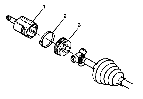
Important: Ensure the trilobal tri-pot bushing is flush with the face of the housing.
7. Place approximately 1/2 of the grease from the service kit in the wheel drive shaft inboard seal. Use the remainder of the grease to repack the housing.
8. Install the trilobal tri-pot bushing (3) to the housing (1).
9. Position the larger new seal retaining clamp (2) on the wheel drive shaft inboard seal.
10. Slide the housing over the tri-pot joint spider assembly on the wheel drive shaft bar.
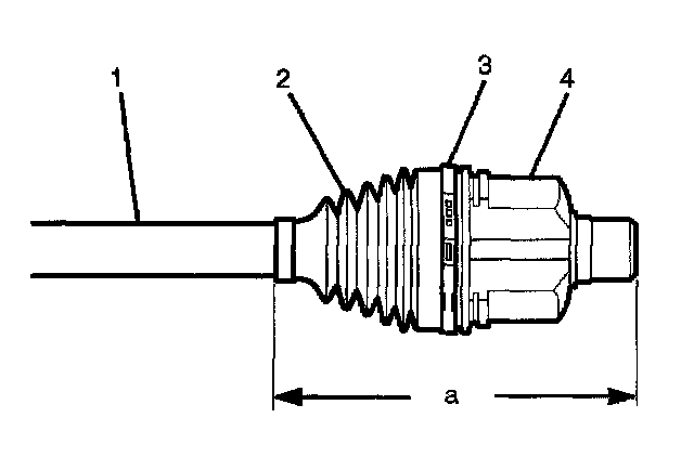
11. Slide the large diameter of the wheel drive shaft inboard seal (2), with the large clamp (3) in place, over the outside of the trilobal tri-pot bushing and locate the lip of the seal in the groove.
Important: The wheel drive shaft inboard seal must not be dimpled, stretched out or out of shape in any way. If the seal is not shaped correctly, carefully insert a thin, flat, blunt tool (no sharp edges) between the large seal opening and the trilobal tri-pot bushing in order to equalize the pressure. Shape the seal properly by hand. Remove the tool.
12. Position the joint assembly at the proper vehicle dimension.
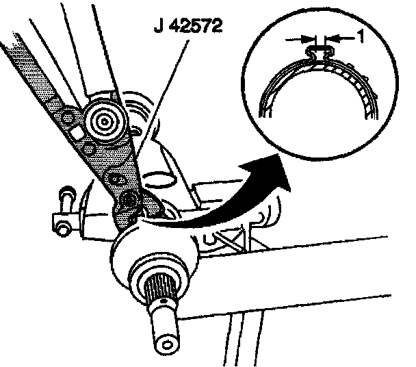
13. Align the following items while crimping the retaining clamp:
^ The wheel drive shaft inboard seal
^ The tri-pot housing
^ The large seal retaining clamp
14. Using the J 42572, crimp the large seal retaining clamp.
^ Tighten the clamp to 136 Nm (100 ft. lbs.).
15. Rotate the inner tri-pot housing 4 or 5 times in order to distribute the grease throughout the tri-pot spider bearings.