Steering Gear Stub Shaft Seals and Bearing Replacement
- Tools Required- J 29810 Stub Shaft Seal Protector Disassembly Procedure
Disassembly Procedure
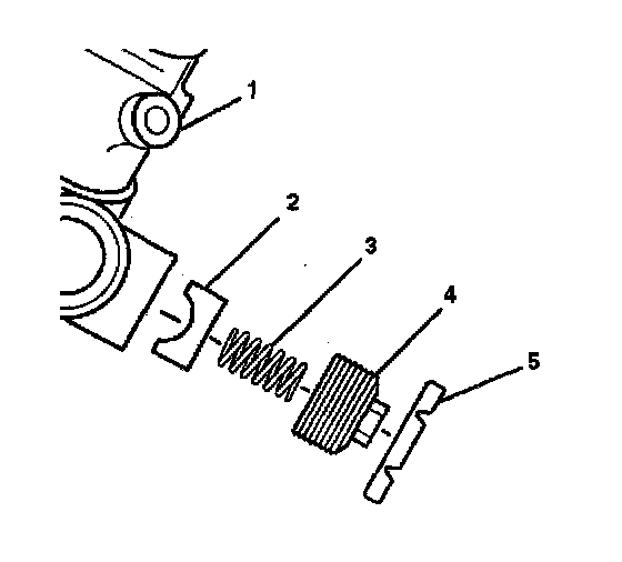
1. Remove the adjuster plug lock nut (5) from the adjuster plug (4).
2. Remove the adjuster plug (4) from the gear assembly (1).
3. Remove the adjuster spring (3) and the rack bearing (2).
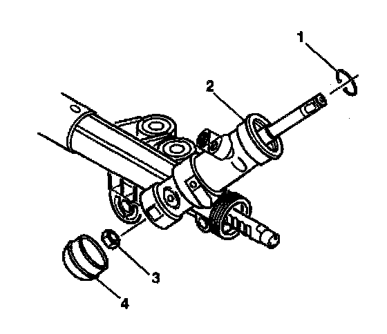
4. Remove the retaining ring (1) from the valve bore of the rack and pinion gear assembly (2).
5. Remove the dust cover (4) from the bottom of the rack and pinion gear assembly (2).
Important: The stub shaft must be held place during the following step:
6. Remove the hex lock nut (3) from the lower end of the pinion and valve assembly while holding the stub shaft with a 14 mm crowfoot wrench.
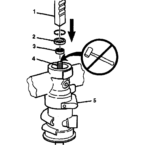
Important: When performing the following procedure, do not remove pinion and valve assembly from the rack and pinion gear assembly (5). Press the pinion and valve assembly only far enough to allow removal of the stub shaft bearing annulus (2) and the stub shaft seal (2).
7. Using an arbor press (1), press on the threaded end of the pinion until removal of the following items is possible:
7.1. The stub shaft (4)
7.2. The stub shaft seal (3)
7.3. The stub shaft bearing annulus assembly (2)
Assembly Procedure
Notice: Refer to Fastener Notice in Service Precautions.
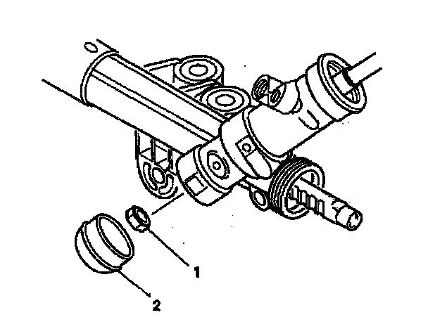
Important: The stub shaft must be held place. during the following step:
1. Install the hex lock nut (1) onto the pinion while holding the valve stub shaft.
- Tighten the hex lock nut (1) to 30 Nm (22 ft. lbs.).
2. Install the dust cover (2) to the rack and pinion gear assembly.
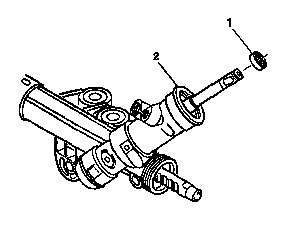
3. Install the stub shaft bearing annulus assembly (1) onto the valve stub shaft (2).
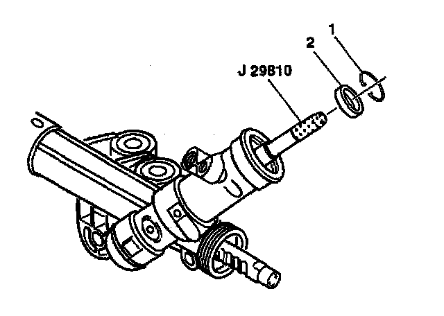
4. Install J 29810 onto the valve stub shaft.
5. Lubricate the stub shaft seal (2) with grease.
6. Install the stub shaft seal (2) into the rack and pinion gear assembly.
7. Install the retaining ring (1) into the groove in the rack and pinion gear assembly.
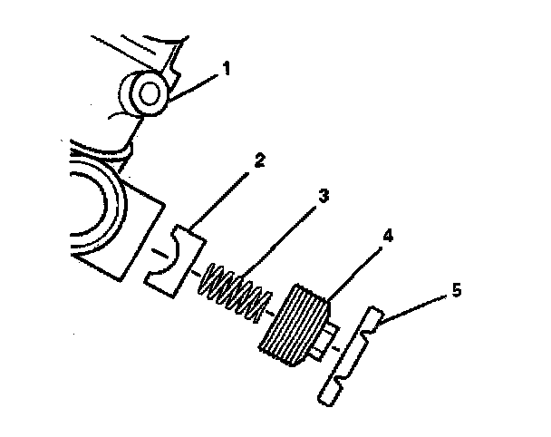
8. Lubricate the following items with lithium base grease:
8.1. The rack bearing (2)
8.2. The adjuster spring (3)
8.3. The adjuster plug (4)
9. Install the following items into the gear assembly:
9.1. The rack bearing (2)
9.2. The adjuster spring (3)
9.3. The adjuster plug (4)
10. Turn the adjuster plug (4) clockwise onto the rack and pinion gear assembly (1) until the adjuster plug (4) bottoms in the rack and pinion gear assembly (1), then turn the adjuster plug (4) back 50 degrees to 70 degrees.
11. Check the rotational torque on the pinion. The maximum pinion preload torque is 1.8 Nm (16 inch lbs.).
12. Install the adjuster plug lock nut (5) to the adjuster plug (4).
- Tighten the adjuster plug lock nut (5) to 68 Nm (50 ft. lbs.) while holding the adjuster plug (4) stationary.
Important: Flush and bleed power steering system (hoses, reservoir and cooler lines) with power steering fluid GM Part #1050017 (or equivalent meeting GM Specification #9985010).